


Quick Research
Generate reliable direction feasibility study reports for your R&D in just a few steps.

Technical Q&A
Discover and master advanced knowledge NOW. Basics, ideas, possibilities, all at once.

Find Solutions
As an expert in R&D theories, this can generate solutions to your technical problems instantly.

Evaluate Feasibility
Analyze your overall solution with one click, know your potential R&D risks in advance.

Monitor Landscape
Get weekly tech updates, stay abreast of the latest tech innovations and key insights.
Steam turbine generator set maintenance barring gear
A turbogenerator set, inspection and maintenance barring technology, applied in the direction of engine components, machines/engines, mechanical equipment, etc., can solve the problems of inconvenient installation, assembly and disassembly, etc., and achieve the effect of simple assembly and disassembly, good rigidity and light weight
- Summary
- Abstract
- Description
- Claims
- Application Information
AI Technical Summary
Problems solved by technology
Method used
Image

Examples
Embodiment 1
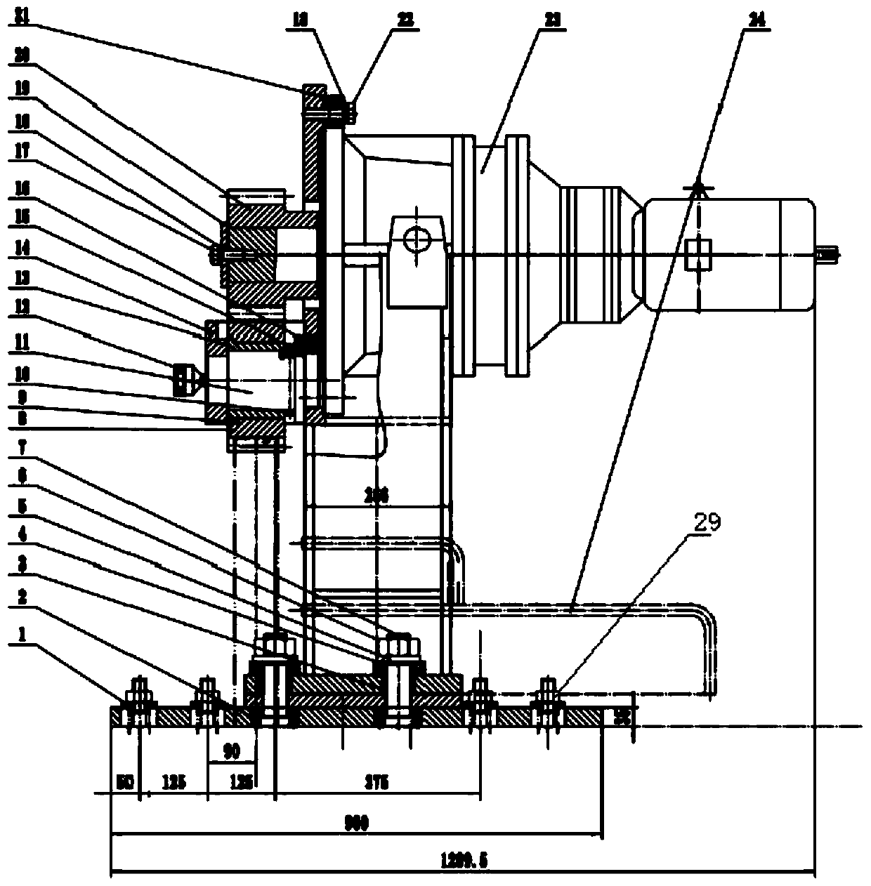
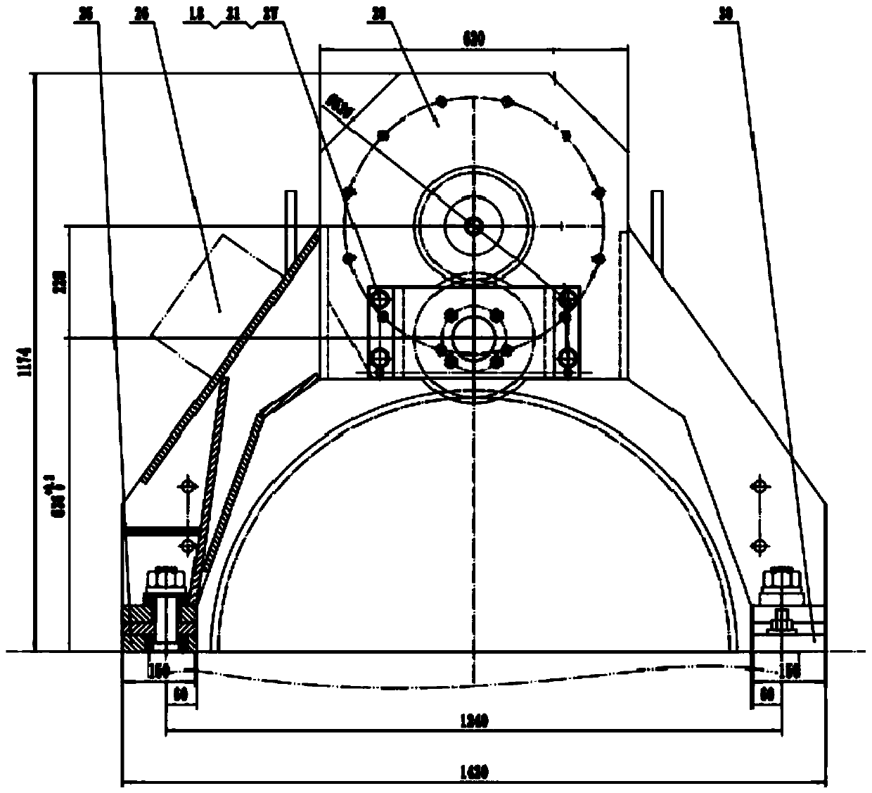
[0016] Such as Figure 1-2 As shown, a turbogenerator set maintenance barring includes a left bracket 25, a right bracket 30, a crossbeam 28, a cycloidal pinwheel reducer 23 and a storage bracket 24, and the tops of the left bracket 25 and the right bracket 30 are installed by The fastening bolt 7 is installed in the hole, and the top of the fastening bolt 7 runs through the bottom of the installation crossbeam 28, and the top of one side of the crossbeam 28 is installed with a cycloidal pinwheel reducer 23 through the No. 1 bolt 22, and one end of the cycloidal pinwheel reducer 23 It has a direct-coupled motor, and the other end of the cycloid reducer 23 is clamped with the driving gear 20 around the rotating shaft, and one end of the rotating shaft is installed with a shaft end retaining ring 19 through the second bolt 17, and the transition shaft 11 is welded at the bottom of the driving gear 20 A transition gear 8 is set on the periphery of the transition shaft 11, and the...
Embodiment 2
[0022] Such as Figure 1-2 As shown, a turbogenerator set maintenance barring includes a left bracket 25, a right bracket 30, a crossbeam 28, a cycloidal pinwheel reducer 23 and a storage bracket 24, and the tops of the left bracket 25 and the right bracket 30 are installed by The fastening bolt 7 is installed in the hole, and the top of the fastening bolt 7 runs through the bottom of the installation crossbeam 28, and the top of one side of the crossbeam 28 is installed with a cycloidal pinwheel reducer 23 through the No. 1 bolt 22, and one end of the cycloidal pinwheel reducer 23 It has a direct-coupled motor, and the other end of the cycloid reducer 23 is clamped with the driving gear 20 around the rotating shaft, and one end of the rotating shaft is installed with a shaft end retaining ring 19 through the second bolt 17, and the transition shaft 11 is welded at the bottom of the driving gear 20 A transition gear 8 is set on the periphery of the transition shaft 11, and the...
PUM
 Abstract
Description
Claims
Application Information
 - R&D Engineer
- R&D Manager
- IP Professional
- Industry Leading Data Capabilities
- Powerful AI technology
- Patent DNA Extraction
Browse by: Latest US Patents, China's latest patents, Technical Efficacy Thesaurus, Application Domain, Technology Topic, Popular Technical Reports.
© 2024 PatSnap. All rights reserved.Legal|Privacy policy|Modern Slavery Act Transparency Statement|Sitemap|About US| Contact US: help@patsnap.com