Automatic intelligent cleaning device

A technology for intelligent cleaning and rotating shafts, applied in chemical instruments and methods, cleaning methods and utensils, cleaning methods using liquids, etc. Stable, stable and reliable structure, compact structure

Pending Publication Date: 2019-08-23
因而克智能科技(浙江)有限公司
View PDF1 Cites 5 Cited by
  • Summary
  • Abstract
  • Description
  • Claims
  • Application Information

AI Technical Summary

Problems solved by technology

[0004] Although the cleaning machines on the market can achieve the purpose of cleaning the dirt on the surface of the object, their automation is low, and manual cleaning operations are required on site.
As we all know, the environment of animal husbandry factories is dirty and messy, and the smell is unpleasant, which brings great inconvenience to the staff on-site manual operation
In addition, for some relatively regular workshop environments or large-scale machinery and equipment with fixed geometric shapes, manual cleaning operations are labor-intensive and labor-intensive, so automatic cleaning instead of manual cleaning is the future trend

Method used


Image

  • Automatic intelligent cleaning device
  • Automatic intelligent cleaning device
  • Automatic intelligent cleaning device

Examples


Embodiment 1

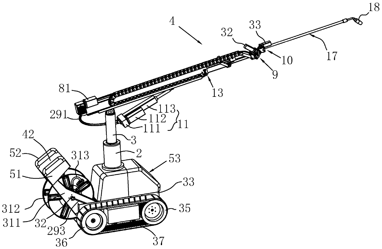
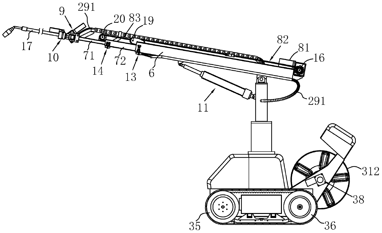
[0055] as attached figure 1 , 2 The automatic intelligent cleaning device shown in and 11 comprises a mobile trolley 1, a horizontal rotating base 2 standing on the mobile trolley 1, a main rotating shaft 3 that is rotatably connected to the horizontal rotating base 2, and a cleaning machine located on the main rotating shaft 3. arm 4. The horizontal rotating base 2 is provided with a first driving motor 5 for driving the main rotating shaft 3 to rotate.

[0056] Wherein, the cleaning arm 4 includes a main arm 6, a telescopic arm 7 arranged on the main arm 6, a telescopic drive mechanism 8 for driving the telescopic arm 7 to expand and contract, a spray bar 17 arranged at one end of the telescopic arm 7 away from the main rotating shaft 3, a driving spray The rotary drive mechanism 9 for the vertical rotation of the rod 17, and the rotary drive mechanism 10 for driving the spray rod 17 to rotate in the circumferential direction. The end of the spray rod 17 away from the rot...

Embodiment 2

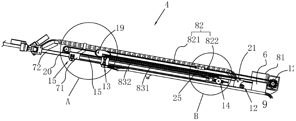
[0091] The difference between the second embodiment and the first embodiment lies in that the structure of the connection between the first transmission chain 831 , the second transmission chain 832 and the main arm 6 and the secondary telescopic arm 72 in the second embodiment is different.

[0092] as attached figure 1 , 12 As shown in and 13, the second tightening mechanism 26 includes a first electric telescopic rod 61, one end of the first electric telescopic rod 61 is fixed on the end of the main arm 6 close to the second driven wheel 20, and the other end is connected to the first driven chain . The end of the second guide part 14 away from the secondary telescopic arm 72 is provided with a second electric telescopic rod 62 , and the telescopic rod of the second electric telescopic rod 62 is connected with the third transmission chain. Wherein, both the first electric telescopic rod 61 and the second electric telescopic rod 62 are electrically connected to the control...


PUM


Abstract

The invention provides an automatic intelligent cleaning device which comprises a movable trolley, a horizontal rotating seat, a main rotary shaft and a cleaning arm arranged on the main rotary shaft,wherein a first driving motor is arranged on the horizontal rotating seat; the cleaning arm comprises a main arm, a telescopic arm, a telescopic driving mechanism, a spray boom, a rotating driving mechanism driving the spray boom to vertically rotate, and a rotation driving mechanism driving the spray boom to rotate in the circumferential direction of the spray boom; a sprayer is arranged on thespray boom; the other end of the spray boom is connected with a water supply pipe; the main arm is hinged to the top end of the main rotary shaft; a lifting driving mechanism driving the main arm to lift is arranged on the main rotary shaft; a control system is arranged on the movable trolley; and the first driving motor, the telescopic driving mechanism, the rotating driving mechanism, the rotation driving mechanism and the lifting driving mechanism are electrically connected with the control system. The automatic intelligent cleaning device is high in degree of automation and can replace manual operation to automatically clean in the site environment; and the cleaning arm is in multi-axis linkage, high in flexibility, wide in cleaning range and excellent in effect.

Description

technical field [0001] The invention relates to the technical field of cleaning equipment, in particular to an automatic intelligent cleaning device. Background technique [0002] With the development of social science and technology, the application of automation equipment in daily life is becoming more and more extensive. High-pressure cleaning devices are mainly used to clean the surface of large equipment, factory workshop environment, animal husbandry factory environment, etc. It can peel off and wash away the dirt to achieve the purpose of cleaning the surface of the object. [0003] As shown in the patent No. CN106040646B, named high-pressure cleaning machine and CN105170516A, patent named high-pressure cleaning machine, most of the high-pressure cleaning equipment on the market includes racks, power units, high-pressure water pumps, spray bars, etc.; When working, the operator holds the spray bar to clean the surface of the target cleaning object, and needs to manu...

Claims


Application Information

Patent Timeline
Patent Type & Authority Applications(China)
IPC IPC(8): B08B3/02B08B13/00
CPCB08B3/02B08B13/00
Inventor 郑辉金卫平陶东东阮欣琪
Owner 因而克智能科技(浙江)有限公司
Why Eureka
Try Eureka