
Battery testing device and using method thereof

A technology for battery testing and testing units, applied in measuring devices, using liquid/vacuum for liquid tightness measurement, measuring electricity, etc., can solve problems affecting test accuracy, high and low temperature resistance, delaying research and development progress, etc., to achieve Realize high and low temperature variable temperature test, realize the effect of corrosion resistance

Active Publication Date: 2019-08-20
SHENZHEN GRADUATE SCHOOL TSINGHUA UNIV
View PDF8 Cites 3 Cited by
  • Summary
  • Abstract
  • Description
  • Claims
  • Application Information

AI Technical Summary

Problems solved by technology

[0003] 1. Most of the existing test devices are built and assembled with organic materials. During the battery test process, the organic materials are easily attacked by the electrolyte and corroded, thus destroying the device, which makes the device components need to be replaced frequently or the device is directly scrapped.
More importantly, the gas produced by the corrosion of organic materials also has a negative impact on battery performance, affecting the accuracy of the test;
[0004] 2. Existing testing devices can generally only test one battery, and cannot conduct parallel experiments on multiple batteries (samples), thus delaying the research and development progress;
[0006] 4. Existing test devices cannot realize variable temperature tests, especially high temperature tests (existing test devices are mostly assembled and constructed of organic materials, which are not resistant to high and low temperatures)
[0007] 5. The air pressure in the test device cannot be accurately monitored
[0012] So far, there is no test device that can be used to test metal ion batteries using solid electrolytes at the same time, and can control the pressure applied to the battery steplessly, and can realize high temperature testing of the battery, and at the same time can realize multiple batteries to test

Method used


Image

  • Battery testing device and using method thereof
  • Battery testing device and using method thereof
  • Battery testing device and using method thereof

Examples


Embodiment 1

[0069] First assemble the lithium-oxygen button cell in the glove box. Specifically: a commercial Li sheet (diameter 16mm, thickness 1mm) is used as the negative electrode, Super P (SP) carbon material is used as the conductive agent, La0.85Ca0.15Cr0.85O3@Ru (LCC@R) is used as the positive electrode catalyst, Whatman GF / D Glass fiber as diaphragm, CF 3 SO 3 Li / TEGDME is the electrolyte to assemble the battery. Among them, Super P, La 0.85 Ca 0.15 Cr 0.85 o 3 @Ru and the binder PVDF are coated on the nickel foam according to the ratio of 6:3:1 to prepare the positive electrode sheet. The assembled lithium-oxygen battery is tested with a battery testing device 1, Figure 4 The lithium-oxygen battery measured for an embodiment of the present invention is at room temperature charge and discharge electrochemical performance diagram, SP+La 0.85 Ca 0.15 Cr 0.85 o 3 The discharge platform of a lithium-oxygen battery with @Ru as the positive electrode is around 2.6V, and th...


PUM

PropertyMeasurementUnit
diameteraaaaaaaaaa

Abstract

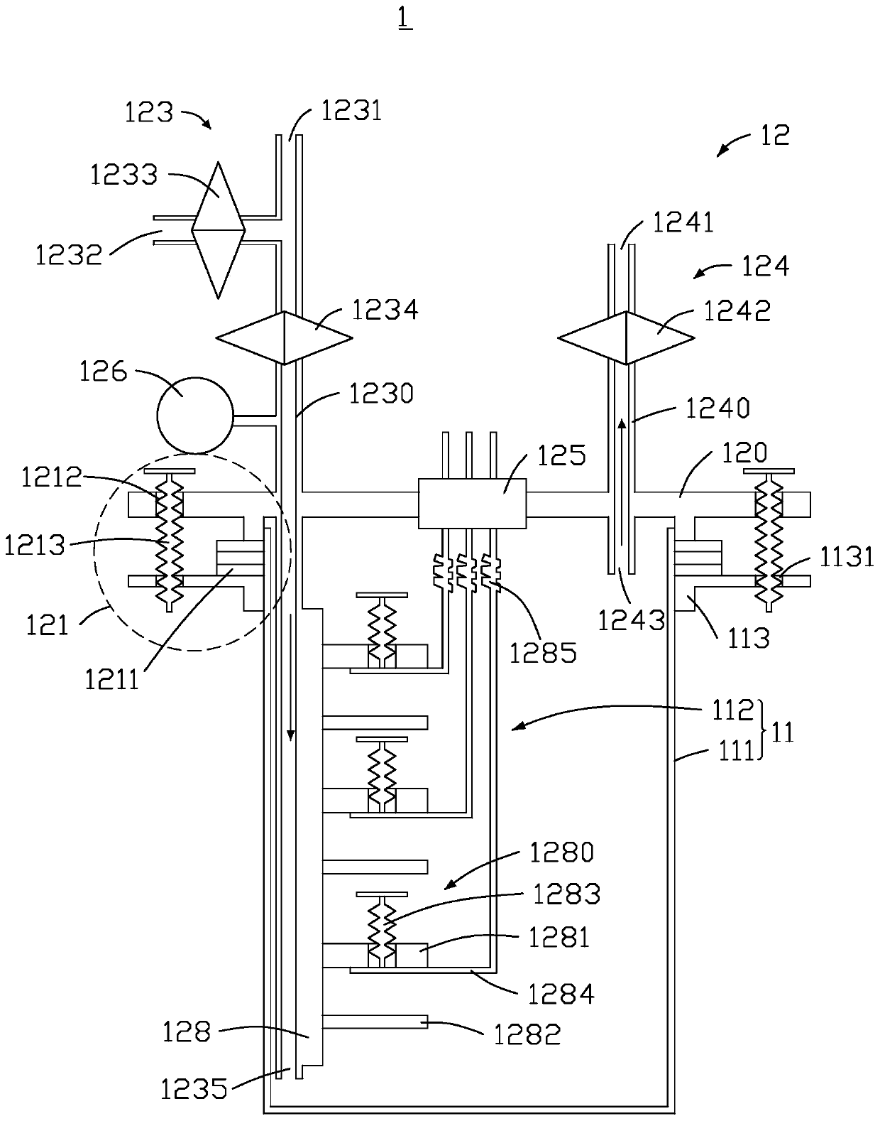
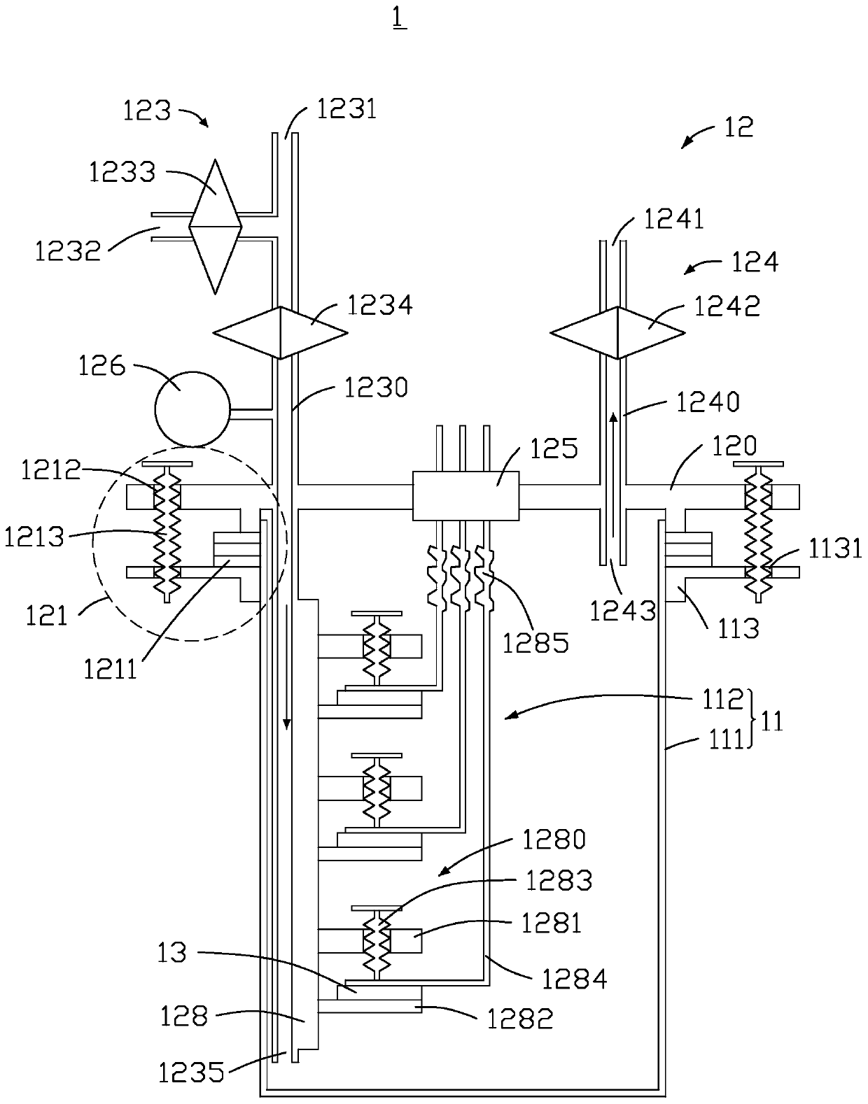
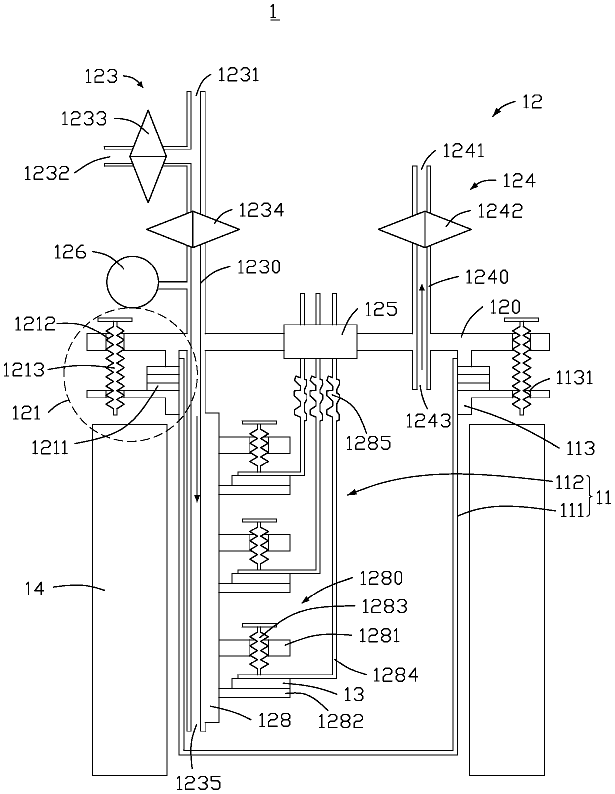
The invention discloses a battery testing device, which comprises a casing and a function module, wherein the casing comprises a shell and an accommodating cavity; one end of the shell is provided with an opening; the shell is internally provided with the accommodating cavity; the function module comprises a supporting frame, a first pipeline assembly, a second pipeline assembly, an aviation jointand multiple testing units; the supporting frame is buckled at the opening; the aviation joint is arranged on the supporting frame; the first pipeline assembly and the second pipeline assembly pass through the supporting frame; at least part of the first pipeline assembly and the second pipeline assembly is located in the accommodating cavity; the first pipeline assembly comprises a first metal valve and a second metal valve; the second pipeline assembly comprises a third metal valve; the first metal valve, the second metal valve and the third metal valve are arranged outside the accommodating cavity; the supporting frame, the first pipeline assembly and the second pipeline assembly are used as common electrodes of the battery testing device; and the multiple testing units are arranged inside the accommodating cavity. The invention also provides a using method for the battery testing device,.

Description

technical field [0001] The invention relates to the field of batteries, in particular to a battery testing device and a using method thereof. Background technique [0002] A metal fuel cell is a rechargeable energy storage battery that uses metal (alkali metal or alkaline earth metal) as fuel and gas (oxygen, carbon dioxide, etc.) as oxidant. Metal fuel cells have the advantages of high power generation efficiency and high energy density, and are considered to be one of the most promising battery technologies in the next generation of energy storage batteries. During the discharge process of metal fuel cells, metals react with oxidizing gases to form solid products; during charging, the solid products decompose to release metals and oxidizing gases. The research on metal fuel cells is still in its infancy. To develop metal fuel cells, it is first necessary to establish a reliable battery test platform and design a stable battery test device. In order to avoid the impact of...

Claims


Application Information

Patent Timeline
Patent Type & Authority Applications(China)
IPC IPC(8): G01R31/385G01L11/00G01M3/26
CPCG01L11/00G01M3/26G01R31/385
Inventor 韩达翟登云贺艳兵王海帆雷宇李宝华康飞宇
Owner SHENZHEN GRADUATE SCHOOL TSINGHUA UNIV
Learn More