Automatic shearing system, automatic shearing method and automatic production line for steel grid plate as well as manufacturing method

A steel grating and shearing head technology, applied in the field of steel grating automatic shearing system, can solve the problems of lack of automatic feeding mechanism, low production efficiency, troublesome operation, etc.

Pending Publication Date: 2019-08-20
冯艳
View PDF1 Cites 4 Cited by
  • Summary
  • Abstract
  • Description
  • Claims
  • Application Information

AI Technical Summary

Problems solved by technology

[0013] The technical problem to be solved by the present invention is to overcome the deficiencies in the prior art. An automatic shearing system for steel gratings, an automatic shearing method, an automatic production line and a preparation method mainly solve the problem of "for different The demand for model steel grating, the need to replace the knives or adjust the gap between the knives, the operation is very troublesome and the lack of automatic feeding mechanism leads to low production efficiency" technical problems

Method used


Image

  • Automatic shearing system, automatic shearing method and automatic production line for steel grid plate as well as manufacturing method
  • Automatic shearing system, automatic shearing method and automatic production line for steel grid plate as well as manufacturing method
  • Automatic shearing system, automatic shearing method and automatic production line for steel grid plate as well as manufacturing method

Examples


Embodiment 1

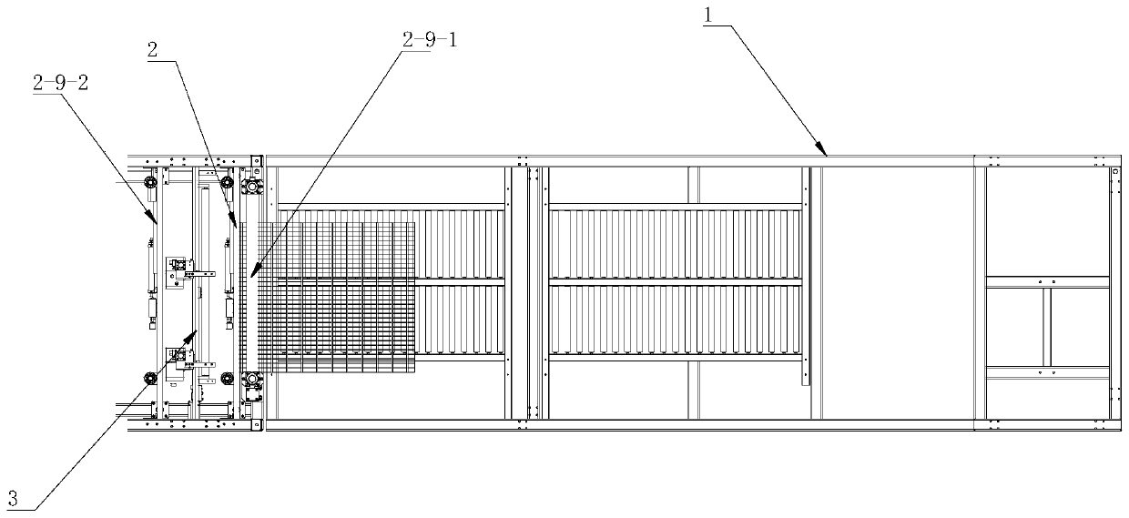
[0098] An automatic steel grating shearing system, comprising a base 1 on which a feeding mechanism 2 and a shearing device 3 are installed,

[0099] Among them, refer to figure 2 and image 3 As shown, the feeding mechanism 2 includes an upper drum 2-1 and a lower drum 2-2. The lower drum 2-2 is driven to rotate by the first power device, and the upper drum 2-1 is arranged on the lower drum 2-2. 2. The upper part is driven by the second power device to move up and down to loosen or compress the workpiece 2-8 between the upper roller 2-1 and the lower roller 2-2.

[0100] continue to refer figure 2 and image 3 As shown, the first power device includes a drive motor 2-3 and a reducer 2-4, and the drive motor is connected to the lower drum 2-2 through the reducer 2-4 to drive the lower drum 2-2 rotate.

[0101] continue to refer figure 2 and image 3 As shown, the second power device includes a pressing cylinder 2-5, and the pressing cylinder 2-5 is connected to the u...

Embodiment 2

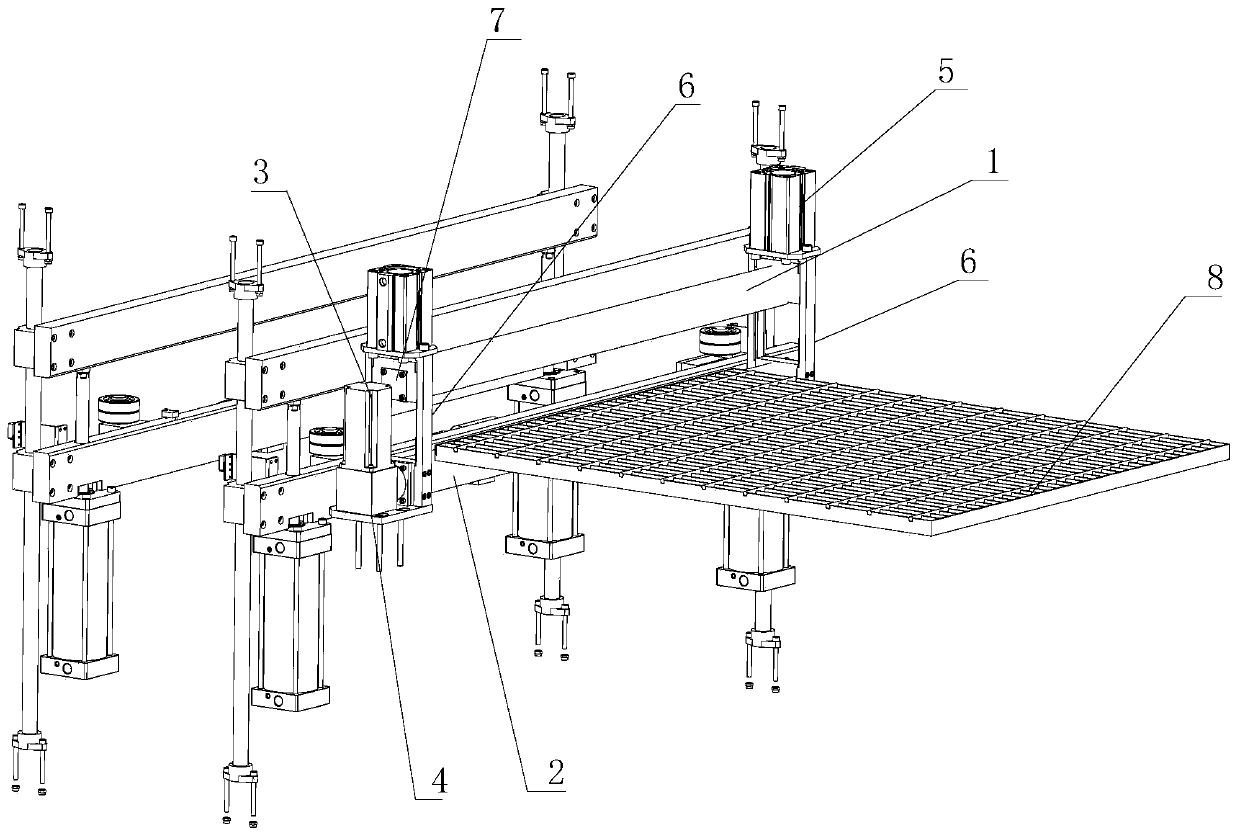
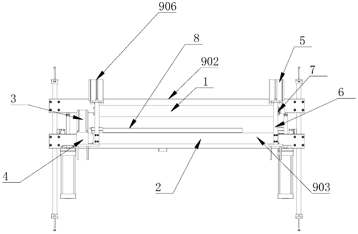
[0127] refer to Figure 10 As shown, an automatic steel grating production line includes the steel grating automatic shearing system as described in Embodiment 1, and an edge-sealing welding mechanism 4 is also installed on the base 1, and the edge-sealing welding mechanism 4 includes an edge sealing welding clamping mechanism 5 for fixing steel grating workpieces;

[0128] Preferably, on the base 1 , a workpiece transmission mechanism 5 is installed between the edge sealing welding mechanism 4 and the shearing device 3 .

[0129] In the specific implementation, after the steel grating workpiece (the workpiece that has been welded with flat steel) is cut, it enters the edge-sealing welding mechanism for edge-sealing welding, and finally processed into a finished steel grating. The perfectly coordinated production line has the advantages of high processing quality, high efficiency, and low cost for line replacement.

Embodiment 3

[0131] Based on the automatic steel grating shearing system described in Embodiment 1, this embodiment provides an automatic steel grating shearing method, including the following steps:

[0132] Step 1: Feeding: the steel grating workpiece enters between the upper roller and the lower roller, the pressing cylinder drives the upper roller to press the steel grating workpiece tightly, and the lower roller rotates to realize feeding;

[0133] Step 2: Measuring the transportation distance: use the travel sensor device to measure the transportation distance of the steel grating workpiece;

[0134] Step 3: Clamping: Determine whether the steel grating workpiece has entered the area where the clamping mechanism is located by the distance detected by the stroke sensor device. After entering the area, it is controlled by the controller:

[0135] The lower drum stops rotating and feeding,

[0136] The upper compression bar presses down to fit the lower compression bar to limit the ste...


PUM


Abstract

The invention discloses an automatic shearing system, an automatic shearing method and an automatic production line for a steel grid plate as well as a manufacturing method. The automatic shearing system comprises a pedestal, wherein a feeding mechanism and a shearing device are mounted on the pedestal; the shearing device comprises a shearing mechanism; the shearing mechanism comprises a mountingplate; an upper shearing head and a lower shearing head which are symmetrical mutually are fixedly mounted on the mounting plate; slot holes are symmetrically formed in the upper shearing head and the lower shearing head; a fixed blade and a movable blade are mounted in the slot holes of the upper shearing head to form shearing angles; the upper shearing head is movably mounted on the mounting plate, and is driven by a Z-direction transmission mechanism to move on the mounting plate; and the shearing mechanism further comprises a power mechanism for pushing the movable blade to move. The automatic shearing system meets shearing requirements of steel grid plates of different models by changing telescopic distance of piston rods of hydraulic cylinders, greatly improves production efficiency, greatly increases a material utilization rate of the steel grid plate, and effectively improves production environment.

Description

technical field [0001] The invention relates to the technical field of steel grating equipment, in particular to an automatic steel grating shearing system. Background technique [0002] At present, in the field of steel grating processing and production, cutting is one of the essential processes in the process of steel grating processing. [0003] The most commonly used cutting methods in industrial production can be roughly divided into metal sawing, hydraulic shearing, and flame cutting. 3 major types, each with its own characteristics: [0004] Hydraulic shearing: high production efficiency, low material loss, convenient maintenance, and environmental protection, but the technical difficulty is high, and it has not been applied in actual production at present; [0005] Metal sawing: low efficiency, large loss of material at the saw kerf, high noise, and large dust pollution. In addition, the consumption of saw blades is also a considerable waste; [0006] Flame cuttin...

Claims


Application Information

Patent Timeline
Patent Type & Authority Applications(China)
IPC IPC(8): B23D15/06B23D33/02B23D33/10B23D33/12B23D35/00B21D43/09B21D1/00
CPCB21D1/00B21D43/09B23D15/06B23D33/02B23D33/10B23D33/12B23D35/001
Inventor 冯艳
Owner 冯艳
Why Eureka
Try Eureka