Waterflow-driven water outlet device

A technology of water flow drive and water outlet device, which is applied in the direction of spraying device, spraying device, etc., which can solve the problems of easy slanting of water spray, inability to move the descaling plate normally, and inability to clean scale, etc., to achieve uniform distribution of water spray and excellent shower experience , good descaling effect

Active Publication Date: 2019-08-20
XIAMEN SOLEX HIGH TECH IND CO LTD
View PDF5 Cites 1 Cited by
  • Summary
  • Abstract
  • Description
  • Claims
  • Application Information

AI Technical Summary

Problems solved by technology

In the existing descaling products, the descaling plate moves along the axial direction. In order to ensure the smooth movement of the descaling plate, there must be a certain gap between the thimble and the inner wall of the outlet hole, otherwise the descaling plate will be damaged by the thimble. The friction with the inner wall of the outlet hole is too large to move normally
However, after there is a gap between the thimble and the inner wall of the water outlet, the scale attached to the inner wall of the water outlet cannot be completely removed, resulting in water splashes that are easy to shoot obliquely, and the purpose of cleaning the scale cannot be achieved

Method used


Image

  • Waterflow-driven water outlet device
  • Waterflow-driven water outlet device
  • Waterflow-driven water outlet device

Examples


Embodiment 1

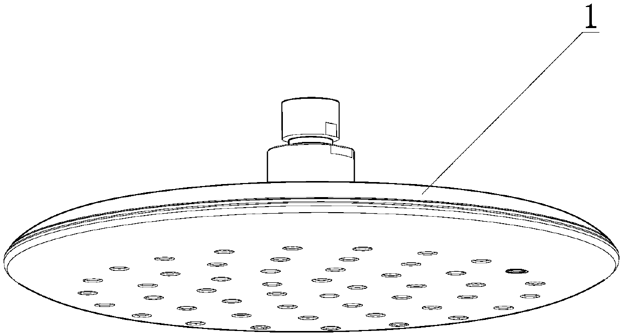
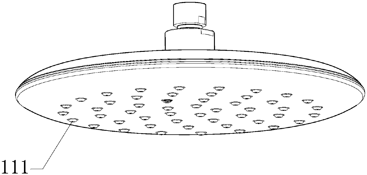
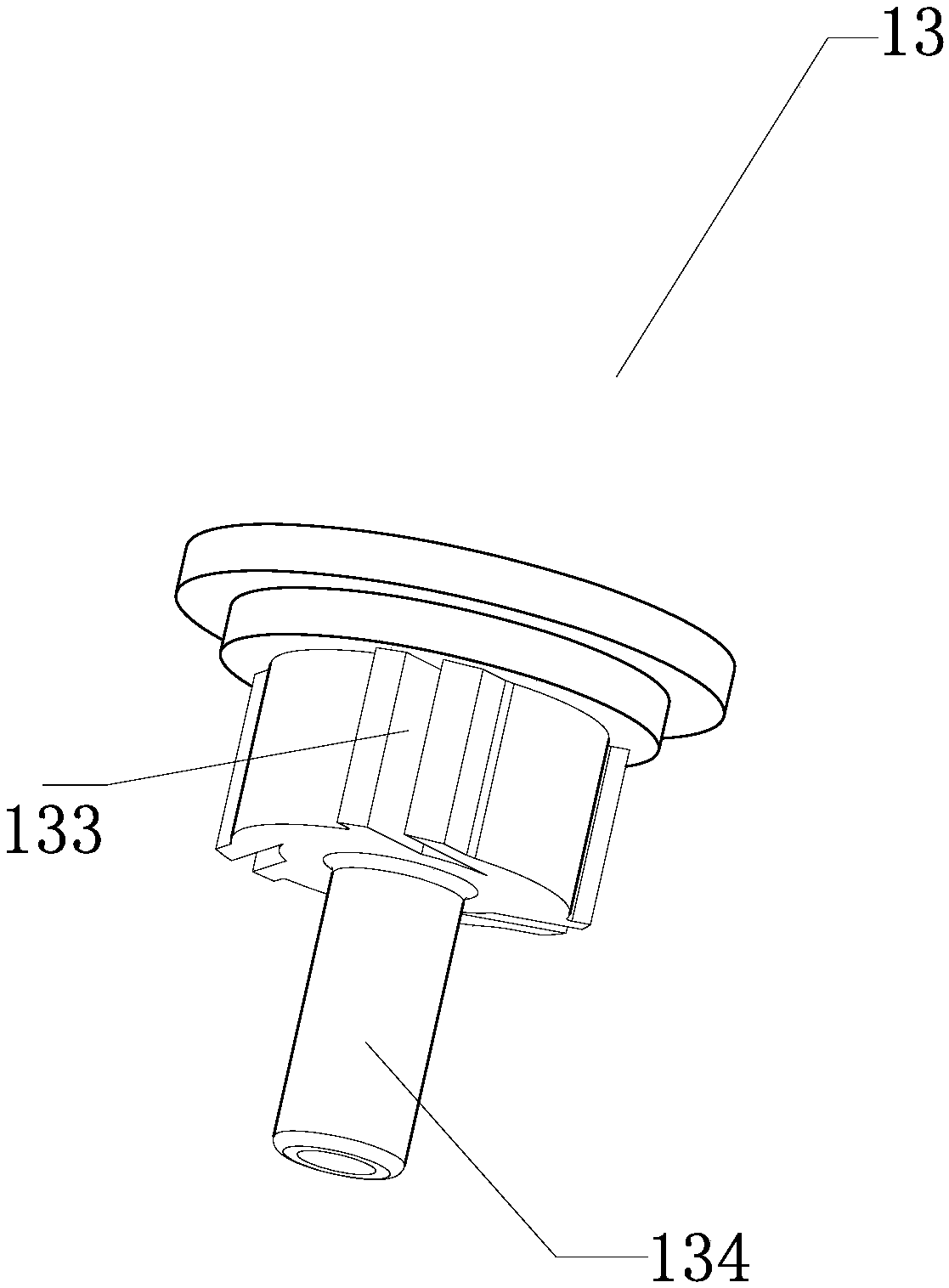
[0031] refer to Figure 1-7 , a water outlet device driven by water flow. In this embodiment, the water outlet device is preferably but not limited to a shower. The shower comprises: a body 1 , a descaling needle plate 2 placed in a cover assembly 11 , and a rotating member 3 driven by water flow to rotate around the axial direction; the cover assembly 11 is located inside the body 1 as a whole. In this embodiment, the oscillating plate is preferably designed as the descaling needle plate 2. In fact, it can also be designed as a simple oscillating plate without descaling effect. Compared with the descaling needle plate, the simple oscillating plate does not have descaling. function, but it also has the effect of changing the water splash.

[0032] The descaling needle plate 2 and the face cover assembly 11 are arranged coaxially and interlockingly along the axial direction, and the descaling needle plate 2 has a plurality of thimbles 21 as spoilers, and the water outlet hole ...

Embodiment 2

[0045] refer to Figure 8 , the difference between this embodiment and embodiment 1 is: in embodiment 1, the descaling needle plate 2 and the face cover assembly 11 are coaxially arranged, and in embodiment 2, the descaling needle plate 2 and the face cover assembly 11 are not coaxially placed , the same technical effect of the present invention can be realized. The structure of other parts is the same as in Embodiment 1.


PUM


Abstract

The invention provides a waterflow-driven water outlet device. The device comprises a body, an oscillating plate arranged in a surface cover assembly, and a rotating component which is driven by waterflow to rotate axially. The oscillating plate and the surface cover assembly are arranged axially in a linked mode, in addition, the oscillating plate is provided with a plurality of turbulent flow components, the surface cover assembly is provided with water outlets which correspond to the turbulent flow components in a one-to-one correspondence mode, and the turbulent flow components stretch into the water outlets correspondingly. The oscillating plate is in oscillating connection with the rotating component. When water enters the water outlet device, waterflow drives the rotating componentto rotate, and accordingly, the rotating component drives the turbulent flow components to oscillate axially in the water outlets in the surface cover assembly correspondingly; one part of the waterflow flows into the surface cover assembly and flows out of the water outlets; and the other part of the waterflow forms axially-downward pushing force on the surface cover assembly, the surface cover assembly is moved downwards axially, and the water outlets are exposed out of the body. According to the water outlet device, in the water outlet process, water scale adhering to the inner walls of thewater outlets is removed, and in a water stop state, the water outlets are hidden in the body.

Description

technical field [0001] The invention relates to a water outlet device. Background technique [0002] The shower head is a kind of shower equipment commonly used in daily life. When the shower head is used for a long time or used in a place with poor water quality, scale is easy to adhere to the hole wall of the water outlet hole on the cover assembly, and the scale will accumulate over time. The water outlet hole is blocked, causing the shower to not work normally. For this reason, many showers with descaling functions have appeared on the market. Generally, a descaling plate with a plurality of descaling needles is installed on the bottom of the shower, and the descaling is driven by manual or water flow. board moves. In the existing descaling products, the descaling plate moves along the axial direction. In order to ensure the smooth movement of the descaling plate, there must be a certain gap between the thimble and the inner wall of the outlet hole, otherwise the desca...

Claims


Application Information

Patent Timeline
Patent Type & Authority Applications(China)
IPC IPC(8): B05B1/18
CPCB05B1/18
Inventor 卓志伟范启华林逢德陈文兴
Owner XIAMEN SOLEX HIGH TECH IND CO LTD
Why Eureka
Try Eureka