Eureka AIR delivers breakthrough ideas for toughest innovation challenges, trusted by R&D personnel around the world.

Lens antenna based on MEMS array

An array lens and antenna technology, which is applied to antennas, antenna arrays, antenna arrays that are energized separately, etc., can solve problems such as poor electronic countermeasures, large cooling requirements, and large power consumption, so as to improve the slow response speed and expand the radiation range. , the effect of enhancing the emission intensity

Active Publication Date: 2019-08-16
CHENGDU UNIV OF INFORMATION TECH
View PDF7 Cites 3 Cited by
  • Summary
  • Abstract
  • Description
  • Claims
  • Application Information

AI Technical Summary

Problems solved by technology

[0003] The electronic scanning radar antenna is based on a phase-controllable array antenna. In addition to the antenna oscillator, each antenna unit also has necessary components such as a phase shifter. Different oscillators can be fed into the Currents of different phases radiate beams with different directions in space; traditional array radars usually use mechanical scanning or electronic scanning, that is, phased array radars, and mechanical scanning radars realize beam scanning by rotating the radar antenna. Affected by mechanical rotation, it has slow response speed, low target update rate, poor resolution, weak versatility, poor electronic countermeasures, large volume, high power consumption, and expensive price. Radar is to flexibly control the beam pointing by controlling the feeding method of the antenna array elements. Its beam pointing is flexible, and it can realize fast scanning without inertia. Controlled array radar is expensive, consumes a lot of power, has a large volume, and requires a lot of cooling

Method used


Image

  • Lens antenna based on MEMS array
  • Lens antenna based on MEMS array
  • Lens antenna based on MEMS array

Examples


Embodiment Construction

[0016] The technical solutions of the present invention will be clearly and completely described below in conjunction with the embodiments. Apparently, the described embodiments are only some of the embodiments of the present invention, not all of them. Based on the embodiments of the present invention, all other embodiments obtained by persons of ordinary skill in the art without creative efforts fall within the protection scope of the present invention.

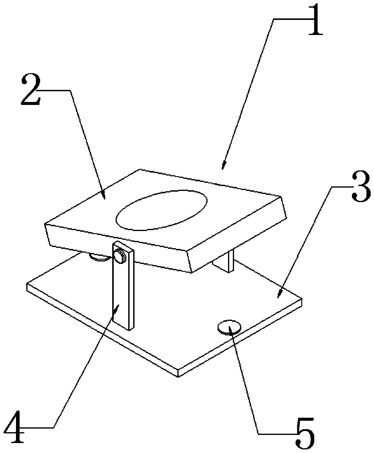
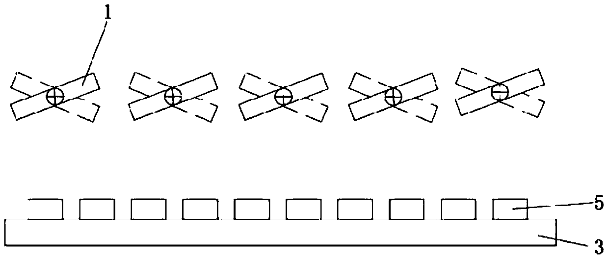
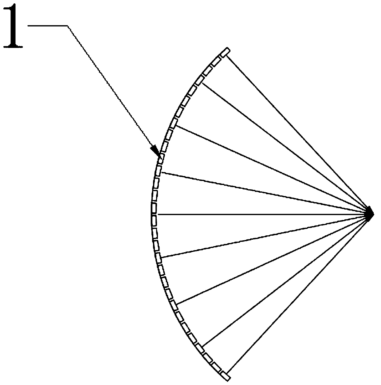
[0017] see Figure 1-4 As shown, a MEMS array lens antenna is characterized in that it includes an antenna array unit 1, each antenna array unit 1 is installed at an angle to the horizontal ground, and several antenna array units 1 are combined to form a concave lens array and a convex lens array Arrangement, the MEMS antenna array unit 1 is made into the form of a lens. The antenna array unit 1 includes an antenna unit 2, a base 3, a rotating mount 4 and an electrode 5. The two sides of the antenna unit 2 are respectively ...


PUM


Abstract

The invention discloses a lens antenna based on a MEMS array. The lens antenna comprises antenna array units. Each antenna array unit is mounted at an angle with the horizontal ground, and multiple antenna array units are arranged into a concave lens array and a convex lens array. The MEMS antenna array units are arranged in the form of lenses, wherein the convex lens antenna array units do not need to rotate and the radiation range of the antenna can be expanded; the concave lens antenna array units converge the generated signals at one point and then transmit them so as to enhance the transmission intensity and realize point-to-point communication; meanwhile, no mechanical rotation is needed, the antenna units are mounted at a certain angle and the radiation surface of the antenna unitshas a larger coverage by the modulated torsion so that the scanning rotation of the beams is realized by the mechanical radar relying on the conventional mechanical rotation can be avoided and the influence of slow reflection speed, low update speed and poor resolution of the mechanical scanning target can be improved.

Description

technical field [0001] The invention relates to the field of communication antennas, in particular to a MEMS-based array lens antenna. Background technique [0002] Traditional array radars usually use mechanical scanning or electronic scanning, that is, phased array radar. The mechanical scanning radar realizes the beam scanning by rotating the radar antenna. Due to the influence of the mechanical rotation, the reaction speed is slow, the target update rate is low, the resolution is poor, the versatility is weak, the electronic countermeasures are poor, the volume is large, and the power consumption High and expensive. Although the electric scanning radar, that is, the phased array radar, flexibly controls the beam pointing by controlling the feeding method of the antenna array elements, its beam pointing is flexible, and it can realize fast scanning without inertia, with high data rate, resolution, versatility and The ability of electronic countermeasures is strong, but ...

Claims


Application Information

Patent Timeline
Patent Type & Authority Applications(China)
IPC IPC(8): H01Q21/29H01Q21/20H01Q3/06H01Q1/12
CPCH01Q1/12H01Q3/06H01Q21/20H01Q21/293
Inventor 叶松姜丹丹马文英丁川陶健
Owner CHENGDU UNIV OF INFORMATION TECH
Why Eureka
Eureka Blog
Learn More