
Transformer

A transformer and card slot technology, applied in the field of transformers, can solve the problems of installation in the preset installation position, the nameplate cannot be adjusted at will, and it is inconvenient for users to view the content of the nameplate, so as to increase friction, facilitate disassembly, and increase the contact area. Effect

Active Publication Date: 2019-08-16
红旗集团温州变压器有限公司
View PDF6 Cites 1 Cited by
  • Summary
  • Abstract
  • Description
  • Claims
  • Application Information

AI Technical Summary

Problems solved by technology

[0003] At present, the nameplate on the transformer is pre-welded with the bottom plate in the middle of the front of the low-voltage side of the transformer corrugated sheet, and then the nameplate is fixed to the bottom plate with screw connectors; however, in practical applications, the installation of the nameplate is often changed according to the installation of the transformer. position, otherwise it would be inconvenient for users to view the contents of the nameplate; therefore, it is unreasonable that the existing installation structure prevents the nameplate from adjusting its position arbitrarily, but can only be installed at the preset installation position

Method used


Image

  • Transformer
  • Transformer
  • Transformer

Examples


Embodiment Construction

[0035] The present invention will be described in further detail below in conjunction with the accompanying drawings.

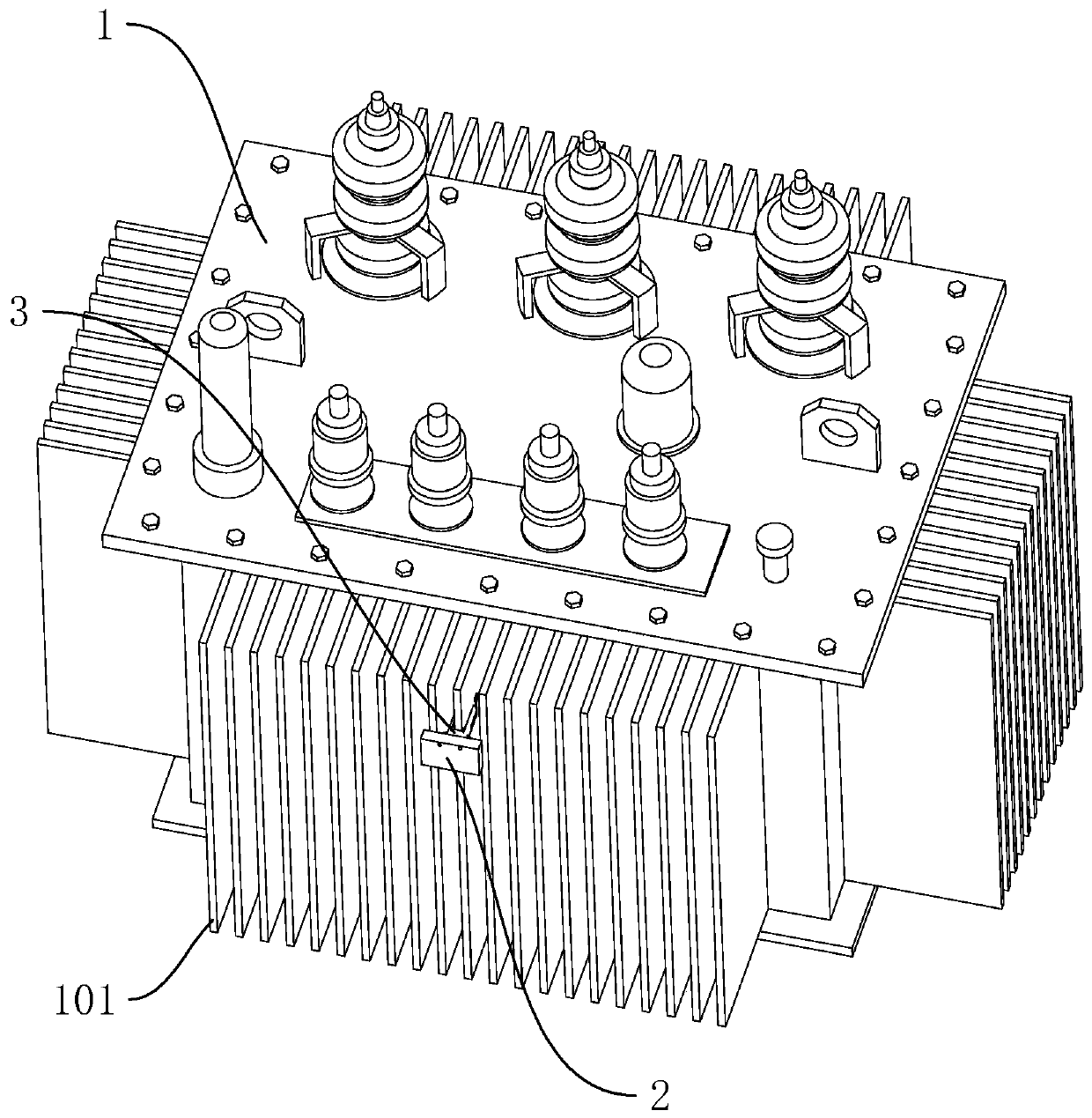
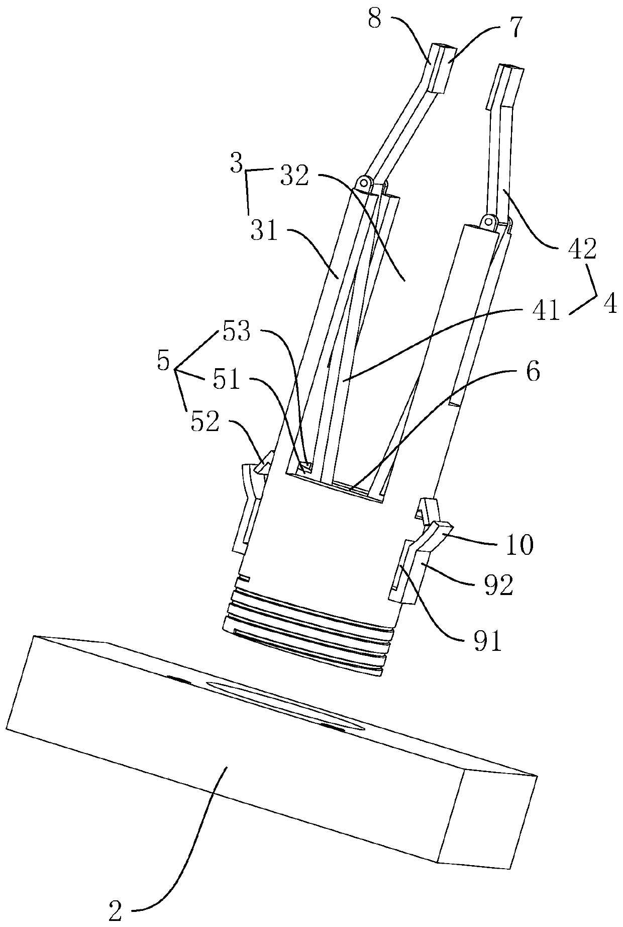
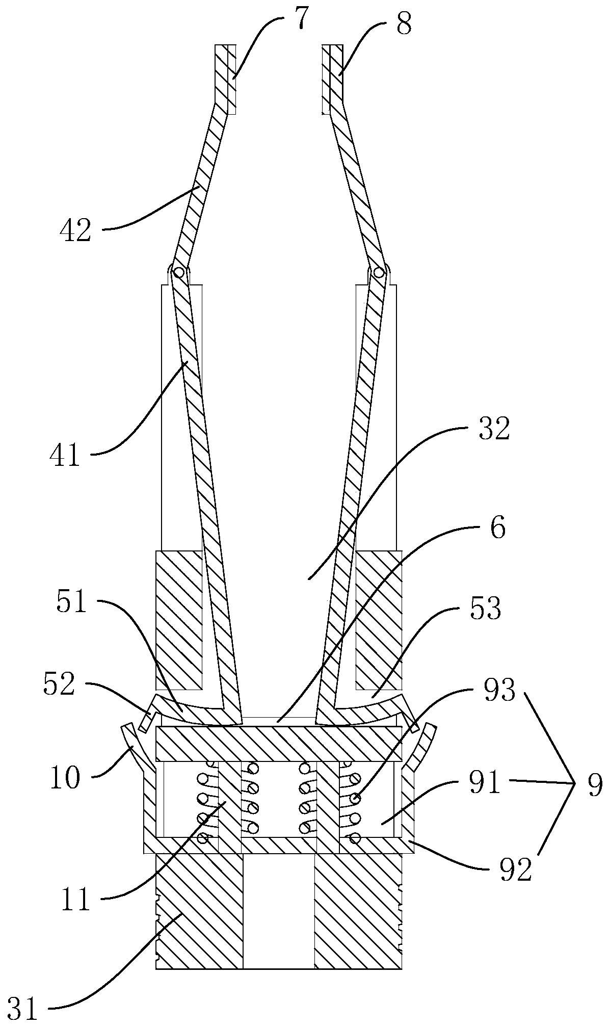
[0036] refer to figure 1 , figure 2 , is a transformer disclosed in the present invention, comprising a transformer body 1, several corrugated sheets 101 arranged longitudinally outside the transformer body, and a mounting plate 2 for installing a nameplate, the mounting plate 2 is detachably connected with connecting accessories facing the side of the transformer body 1 3. The connecting fitting 3 includes a connecting column 31 with a slot 32 , and a self-locking mechanism 4 matching with the corrugated sheet 101 is arranged in the slot 32 , wherein the connecting column 31 is screwed to the mounting plate 2 . After the transformer is installed at the actual installation position, according to the actual situation, the mounting plate 2 of the nameplate is fixedly clamped on the conspicuous position of the corrugated sheet 101 on the side of the transforme...


PUM


Abstract

The invention discloses a transformer and relates to the technical field of transformers to solve the problem that the position of a nameplate cannot be adjusted at random. The transformer comprises atransformer body, a plurality of corrugated plates longitudinally disposed outside the transformer body, and a mounting plate for mounting the nameplate, wherein the mounting plate is detachably connected with a connecting fitting at a side toward the transformer body; the connecting fitting comprises a connecting post having an engagement slot; the engagement slot is provided therein with a self-locking mechanism matching the corrugated plates. The transformer of the invention facilitates the change of the mounting location of the nameplate at any time.

Description

technical field [0001] The invention relates to the technical field of transformers, in particular to a transformer. Background technique [0002] The transformer consists of an iron core (or magnetic core) and a coil. The coil has two or more windings. The winding connected to the power supply is called the primary coil, and the remaining windings are called the secondary coil. It uses the principle of electromagnetic induction to change the AC voltage device. Each transformer needs to be installed with a nameplate to indicate technical data such as the manufacturer's name, rated capacity, rated current, rated voltage, rated impedance, and wiring group. [0003] At present, the nameplate on the transformer is pre-welded with the bottom plate in the middle of the front of the low-voltage side of the transformer corrugated sheet, and then the nameplate is fixed to the bottom plate with screw connectors; however, in practical applications, the installation of the nameplate is...

Claims


Application Information

Patent Timeline
IPC IPC(8): H01F27/00G09F7/20
CPCG09F7/20H01F27/00
Inventor 徐悲鸣马军刘伟王道军史末林伏爱飞
Owner 红旗集团温州变压器有限公司
Learn More