
Composite ignition type combustion light gas gun

A composite ignition type, light gas gun technology, used in compressed air guns, weapons without explosives, weapon types, etc., can solve the problems of rapid reduction of bottom pressure and unsatisfactory launch performance, and achieve excellent performance, simple structure, The effect of increasing the launch speed

Pending Publication Date: 2019-08-16
UNIV OF SCI & TECH OF CHINA
View PDF1 Cites 6 Cited by
  • Summary
  • Abstract
  • Description
  • Claims
  • Application Information

AI Technical Summary

Problems solved by technology

[0007] The purpose of the present invention is to solve the problem of unsatisfactory launch performance due to the rapid decrease of the bottom pressure of the traditional light gas cannon system, to further explore the potential of the combustion detonation drive mode, to improve the launch speed and launch kinetic energy, and to provide a simple structure and Combustion light gas cannon with higher operating efficiency and better performance

Method used


Image

  • Composite ignition type combustion light gas gun
  • Composite ignition type combustion light gas gun
  • Composite ignition type combustion light gas gun

Examples


specific Embodiment approach

[0023] Composite ignition type combustion light gas gun of the present invention, its preferred embodiment is:

[0024] It includes the driving section, the driven section, the converging section and the launch tube connected sequentially from back to front, and also includes the ignition control system as an accessory device;

[0025] The driving section is a straight cylindrical structure with a constant circular inner section, its rear end is closed, and its front opening is connected to the driven section;

[0026] The driven section is also a straight cylindrical structure with a constant circular inner section, and a diaphragm of the driven section is clamped at the connection with the driving section, and the pipe body of the driven section is provided with a pressure measuring hole;

[0027] The converging section is a cylindrical structure with a circular cross-section, its inner diameter gradually decreases continuously and smoothly from the back to the front, and th...

specific Embodiment

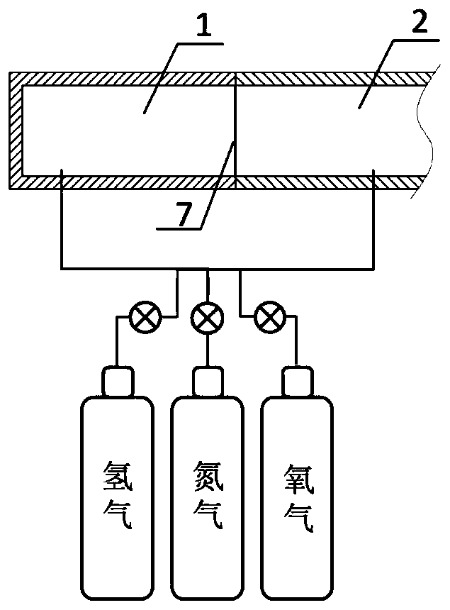
[0046] See attached figure 1 , a compound ignition type combustion light gas gun, which includes: a driving section 1, a driven section 2, a pressure measuring hole 3, a converging section 4, a screw hole 5, a launch tube 6, and is clamped on the driving section 1 and the driven section 2 The driven section diaphragm 7 at the junction, the launch tube diaphragm 8 clamped at the junction of the converging section 4 and the launch tube 6, the projectile 9, and the ignition control system 10.

[0047] The driving section 1 is a straight cylindrical structure with a constant circular inner section, its rear end is closed and its front end is open; the driving section 1 is pre-filled with a certain proportion of hydrogen and nitrogen compressed gas.

[0048] The driven section 2 is a straight cylindrical structure with a constant circular inner section, one end is connected to the driving section 1, the driven section diaphragm 7 is clamped at the connection, and the other end is c...


PUM


Abstract

The invention discloses a composite ignition type combustion light gas gun. The composite ignition type combustion light gas gun comprises a drive section, a driven section, a convergence section, anemitting tube and an ignition control system, wherein one end of the drive section is sealed, and the other end of the drive section is connected to the driven section, and a joint is clamped with a diaphragm; the tube body of the driven section is equipped with a pressure sensor; the front end of the convergence section is connected to the driven section, the rear end of the convergence section is connected to the emitting tube, and the joint of the rear end and the emitting tube is clamped with a diaphragm, and an igniter is mounted on a tube body; a shot is placed on a position, close to the diaphragm, in the emitting tube; and the ignition control system comprises a pressure sensor, a charge amplifier, a digital delay pulse generator. The light gas gun utilizes a composite ignition form, adopts mutual action between detonation waves induced by convergence shock wave reflection and detonation waves forcibly detonated by the igniter to generate intense shock waves, then, the intenseshock waves chase after the shot and are reflected, so that shot-bottom pressure is instantaneously increased, and a gas gun system with higher operation efficiency is developed with a lower price.

Description

technical field [0001] The invention relates to an ultra-high-speed launching light gas gun, in particular to a composite ignition type combustion light gas gun. Background technique [0002] Since the birth of the first light gas cannon, it has become an effective research tool in the fields of aerospace, weaponry and planetary science. Light gas gun is a dynamic high-pressure loading device developed on the basis of traditional artillery firing technology. It relies on the sudden expansion of light gas under high temperature and high pressure to do work on the projectile to achieve a higher firing speed. In recent years, with the continuous expansion of its application fields and the complexity of the model structure, it is required that this ultra-high-speed launch system can have better internal ballistic performance in a wider launch range at a lower cost. [0003] The most widely used at present is the secondary light gas gun. Traditional two-stage light gas guns use...

Claims


Application Information

Patent Timeline
Patent Type & Authority Applications(China)
IPC IPC(8): F41B11/60F41B11/68
CPCF41B11/60F41B11/68
Inventor 侯自豪朱雨建杨基明
Owner UNIV OF SCI & TECH OF CHINA
Learn More