
Axle gear box of material transport cart

A technology for axle gearboxes and transport vehicles, which is applied to gear transmissions, gear lubrication/cooling, belts/chains/gears, etc. It can solve the problems of technology being restricted by people and high cost, and achieve compact space structure, light weight, and low manufacturing cost. The effect of cycle reduction

Pending Publication Date: 2019-08-16
CRCC HIGH TECH EQUIP CORP LTD
View PDF0 Cites 2 Cited by
  • Summary
  • Abstract
  • Description
  • Claims
  • Application Information

AI Technical Summary

Problems solved by technology

[0002] At present, the axle gearboxes used in the loading of large-scale road maintenance machinery products are basically purchased or imported except for a small amount of independent products. Not only the cost is high, but also the technology is controlled by others.

Method used


Image

  • Axle gear box of material transport cart
  • Axle gear box of material transport cart
  • Axle gear box of material transport cart

Examples


Embodiment 1

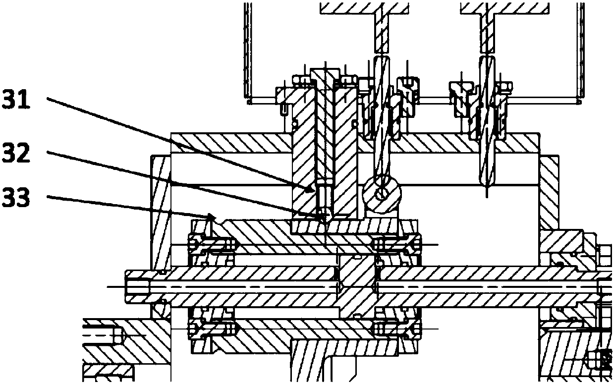
[0029] Embodiment 1.1: a kind of material transport vehicle axle gear box, as figure 1 and Figure 6 As shown, it includes a welding box 2, and a first-stage reduction mechanism 1 is arranged in the welding box 2. The first-stage reduction mechanism 1 includes two gears I and II that mesh with each other, and the gear I is set on the material transport vehicle. On the axle of the wheel, the gear II is installed on the intermediate shaft, and the gear III7 is also set on the intermediate shaft. The gear III7 meshes with the gear IV54, and the gear IV54 is set on the input shaft 6. The gear III and the gear IV form two Stage reduction mechanism, the space between gear IV54 and gear III top is provided with shifting mechanism 3.

[0030] Described gear I, gear II, gear III and gear IV54 are spur gears.

[0031] The shifting mechanism 3 of the axle gear box of the material transport vehicle adopts a built-in oil cylinder to drive a sliding gear shifting mode. The gear IV54 is po...

Embodiment 21

[0044] Embodiment 2.1: A gear-on and off-gear method for the axle gearbox of a material transport vehicle, which includes:

[0045] a. When the control system initiates the shifting action, the left chamber of the shift oil cylinder 52 enters the oil, pushing the oil cylinder body to move to the left, driving the shifting gear on the fork (that is, gear IV) to mesh with the gear III on the intermediate shaft, and the shifting is performed ;

[0046] b. After the shifting is completed, the left chamber of the shifting oil cylinder maintains pressure to maintain the shifting state;

[0047] c. When the control system initiates a disengagement action, oil enters the right chamber of the shift oil cylinder, pushing the oil cylinder body to move to the right, and drives the shifting gear on the fork (that is, gear IV) to disengage from the gear III on the intermediate shaft to perform disengagement ;

[0048] d. After the disengagement is completed, the disengagement state is mai...


PUM


Abstract

The invention relates to an axle gear box of a material transport cart. The axle gear box comprises a box body. A primary reducing mechanism is arranged in the box body and comprises a gear I and a gear II engaged to each other. The gear I is mounted on an axle of a walking wheel of the material transport cart in a sleeving manner, the gear II is mounted on a middle shaft, a gear III is also mounted on the middle shaft in a sleeving manner, the gear III is engaged to a gear IV, the gear IV is mounted on an input shaft in a sleeving manner, the gear III and the gear IV form a secondary reducingmechanism, the gear IV is also connected to a gear shifting mechanism, the gear shifting mechanism also comprises a shift detecting and locking device. The axle gear box has the advantages and effects that the axle gear box is compact in spatial structure and light in weight (totally about 500 KG); the welding box body is thin in wall and good in heat dissipating performance; and the axle gear box can be mounted in a similar product which is lower than the material cart in using strength, wherein the self-driving speed is 0-10 km / h and the coupling operation speed is 120 km / h.

Description

technical field [0001] The invention relates to an axle gearbox and belongs to the technical field of design and manufacture of large-scale railway maintenance machinery. Background technique [0002] At present, the axle gearboxes used for loading large-scale road maintenance machinery products are basically purchased or imported except for a small amount of independent products. Not only the cost is high, but also the technology is controlled by others. With the speed increase of trains and the rapid development of high-speed and heavy-haul railways, large-scale track maintenance machinery is playing an increasingly important role in line maintenance. As an important component of the power bogie of large-scale road maintenance machinery, the axle gearbox is used to provide driving force for the self-propelled and working travel of large-scale road maintenance machinery, and to meet the requirements of train linked operation. [0003] As one of the series products of large...

Claims


Application Information

Patent Timeline
Patent Type & Authority Applications(China)
IPC IPC(8): F16H1/22F16H57/023F16H55/08F16H63/32F16H63/34F16H57/04
CPCF16H1/22F16H57/023F16H55/0806F16H63/32F16H63/34F16H57/0415
Inventor 罗立红孔雪平李家德郭睿
Owner CRCC HIGH TECH EQUIP CORP LTD
Learn More