Fabricated embedded foundation pit retaining pile and pile wall integrated structure and construction method thereof
A technology of foundation pit enclosure and construction method, which is applied in foundation structure engineering, sheet pile wall, excavation, etc., can solve the difficulties of sheet pile transportation, hoisting and installation, unreasonable stress on the section of pile row structure, long construction period, etc. problems, to achieve the effect of good project implementation, high operation efficiency and reduced project cost
- Summary
- Abstract
- Description
- Claims
- Application Information
AI Technical Summary
Problems solved by technology
Method used
Image

Examples
example 1
[0053] Example 1: Prefabricated sheet piles are used as a part of the basement wall in a pile-wall-integrated basement structure
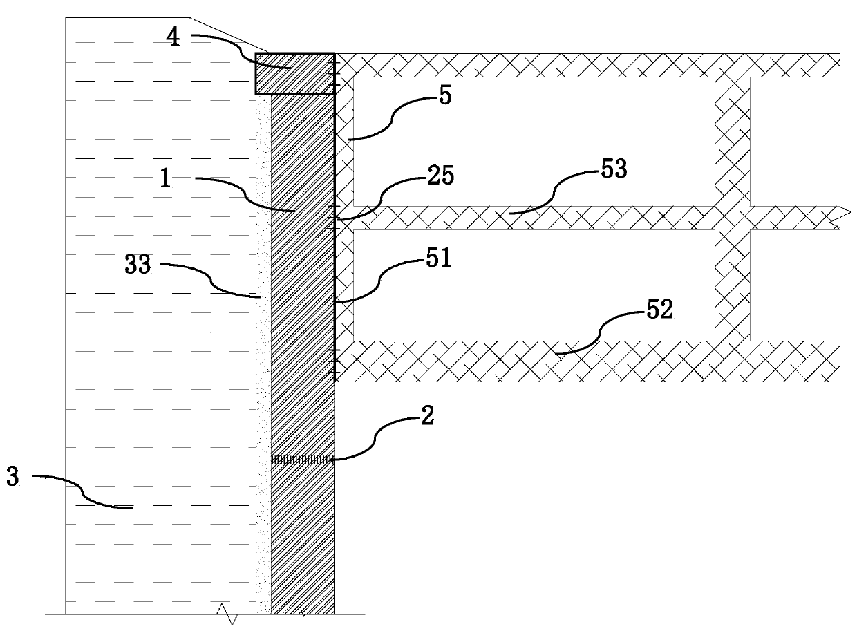
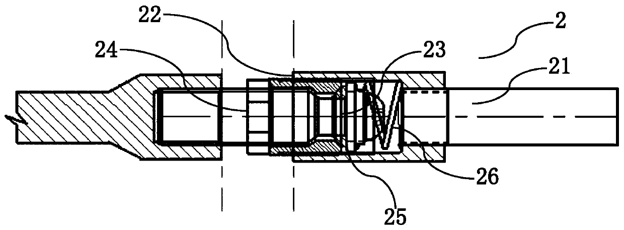
[0054] From figure 1 It can be seen that the foundation pit enclosure structure assembled by the prefabricated sheet pile 1 and the crown beam 4 is used as a part of the outer wall of the basement, and there are pre-embedded steel bar connecting sleeves 25 at different positions of the prefabricated sheet pile 1 to realize the connection with the foundation pit. The steel bar of the bottom plate 52 of the basement and the steel bar in the lining wall 5 are connected as a whole. After the rock-soil body 3 in the foundation pit is excavated, the solidified soil body 33 inside the prefabricated sheet pile 1 and the rock-soil body 3 between the sheet piles are removed, and filled up with cement mortar; hole 25, and link to each other with the reinforcing bars in basement floor 52 steel bars, lining wall 5 and basement roof 53; , the inner lining wall...
example 2
[0055] Example 2. The implantation of prefabricated sheet piles and the method of extending them along the axial direction
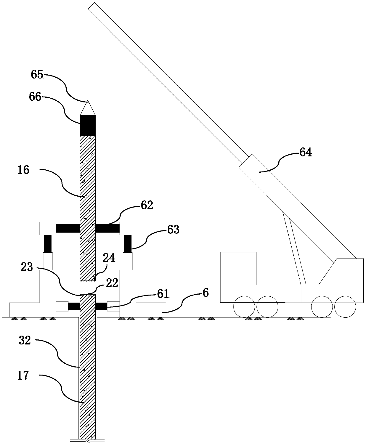
[0056] image 3 The installation base 6 shown as the implantation of the prefabricated sheet pile is composed of the lower section pile clamp 61, the upper section pile clamp 62, the axial pressure device 63, the crane 64, the vibration hammer 65 and the like. From image 3 It can be seen from the figure that in the pre-formed hole 31 or the pre-formed groove 32, the fluid self-setting solidified soil 33 is filled, and the installation base 6 is assembled to the position where the sheet pile 1 is implanted, and the first section of the sheet pile 1 is formed by The crane 64 is hoisted into the upper and lower clamps 61 and 62 of the pedestal 6, and its verticality and position are adjusted through the clamps to ensure that the verticality of the sheet pile 1 is not less than 1 / 300. With the aid of the axial pressing device 63 on the top, the sheet pile...
example 3
[0058] Example 3. Pre-drilled holes (grooves) implanted into sheet piles and soil retaining methods between piles
[0059] Insert the prefabricated sheet pile 1 into the position of the retaining pile of the foundation pit. When the rock and soil mass is relatively hard, a prefabricated hole 31 is required. The diameter of the hole is larger than the maximum size of the prefabricated sheet pile 1 and placed outside 50mm. After the excavation is in place, Stir the mud and dregs in the hole evenly with cement slurry. On the one hand, in order to support the wall of the hole, on the other hand, the solidified soil 33 is formed. The sheet piles 1 implanted in the pre-opening holes 31 mainly include: hollow T-shaped prefabricated sheet piles 11. H-type sheet pile 15 and hollow rectangular plate 18, such as Figure 4 , 5 and 6.
[0060] For different section types of sheet piles 1, different types of holes 41 are reserved in the used crown beam 4, such as Figure 7 , 8 and 9.
...
PUM
 Abstract
Description
Claims
Application Information
 - R&D
- Intellectual Property
- Life Sciences
- Materials
- Tech Scout
- Unparalleled Data Quality
- Higher Quality Content
- 60% Fewer Hallucinations
Browse by: Latest US Patents, China's latest patents, Technical Efficacy Thesaurus, Application Domain, Technology Topic, Popular Technical Reports.
© 2025 PatSnap. All rights reserved.Legal|Privacy policy|Modern Slavery Act Transparency Statement|Sitemap|About US| Contact US: help@patsnap.com