


Quick Research
Generate reliable direction feasibility study reports for your R&D in just a few steps.

Technical Q&A
Discover and master advanced knowledge NOW. Basics, ideas, possibilities, all at once.

Find Solutions
As an expert in R&D theories, this can generate solutions to your technical problems instantly.

Evaluate Feasibility
Analyze your overall solution with one click, know your potential R&D risks in advance.

Monitor Landscape
Get weekly tech updates, stay abreast of the latest tech innovations and key insights.
Positioning drilling equipment for civil engineering buildings
A drilling equipment and civil engineering technology, applied in stone processing equipment, work accessories, manufacturing tools, etc., can solve the problems of increasing the labor level of construction workers, unable to control the drilling accuracy, affecting the installation of exhaust pipes, etc., to avoid deviations , improve stability, reduce the effect of investment
- Summary
- Abstract
- Description
- Claims
- Application Information
AI Technical Summary
Problems solved by technology
Method used
Image

Examples
Embodiment 1
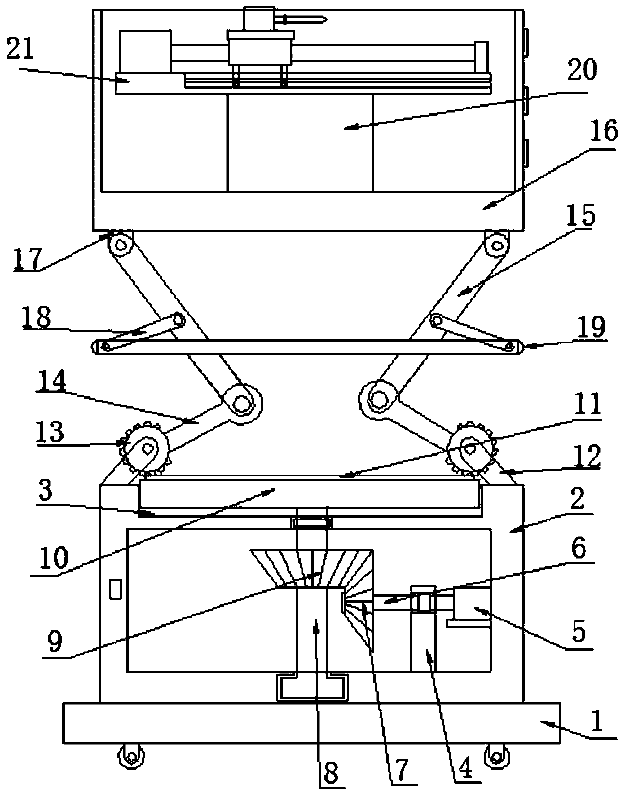
[0028] like Figure 1-5 As shown, the positioning drilling equipment for civil engineering construction according to the embodiment of the present invention includes a base plate 1, and the bottom end of the base plate 1 is provided with a moving wheel, and the moving wheel has a locking function, which facilitates the movement of the device and improves the performance of the device. For flexibility, the top end of the bottom plate 1 is provided with a support box 2, the top end of the support box 2 is provided with a groove 3, the inner bottom end of the support box 2 is provided with a support column 4, and the inner wall of the support box 2 is provided with a supporting column 4. A motor one 5 is provided on one side, and the output shaft of the motor one 5 penetrates the support column 4 and is connected with the rotating shaft 6, and the end of the rotating shaft 6 away from the motor one 5 is provided with a bevel gear one 7, The middle position of the bottom end of th...
Embodiment 2
[0031] like figure 1As shown, in order to make the outer wall of the collection box 16 close to the wall, a plurality of suction cups are provided on one side of the outer wall of the collection box 16, and the two gears 13 are half gears.
[0032] like figure 1 As shown, in order to improve the rotation stability of the rotating shaft 8 , the rotating shaft 8 is set as an inverted T-shaped structure, and the T-shaped end of the rotating shaft 8 extends into the T-shaped groove at the inner bottom end of the support box 2 .
[0033] like figure 1 As shown, in order to improve the rotation flexibility of the rotating shaft 8, a bearing 1 is provided at the joint between the rotating shaft 8 and the inner top of the support box 2. In order to improve the rotation flexibility of the rotating shaft 6, the rotating shaft 6 is connected to the A second bearing is provided at the joint of the support column 4 .
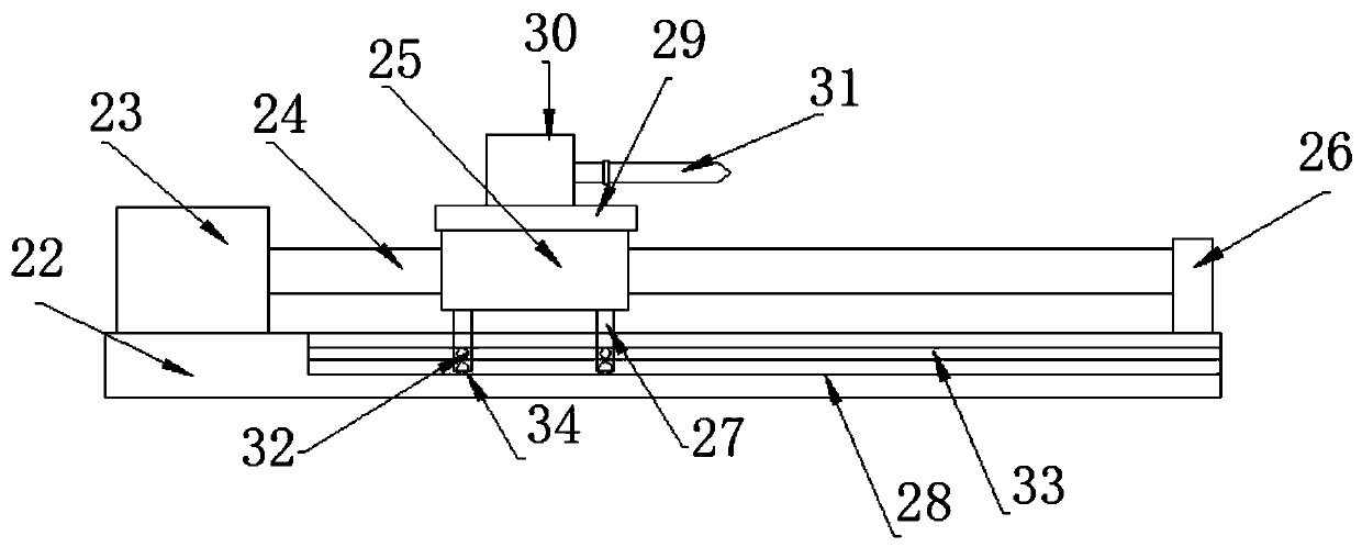
[0034] like figure 1 , 3 As shown, the transmission drilling mecha...
PUM
 Abstract
Description
Claims
Application Information
 - R&D Engineer
- R&D Manager
- IP Professional
- Industry Leading Data Capabilities
- Powerful AI technology
- Patent DNA Extraction
Browse by: Latest US Patents, China's latest patents, Technical Efficacy Thesaurus, Application Domain, Technology Topic, Popular Technical Reports.
© 2024 PatSnap. All rights reserved.Legal|Privacy policy|Modern Slavery Act Transparency Statement|Sitemap|About US| Contact US: help@patsnap.com