Desulfurization and denitrification associated equipment

A supporting equipment, desulfurization and denitrification technology, applied in the direction of cleaning hollow objects, cleaning methods and utensils, chemical instruments and methods, etc., can solve the problems of low reaction efficiency, reduced service life of reactors, waste of chemical solvents, etc., and achieve simple equipment structure , increase work efficiency, efficient cleaning effect

Inactive Publication Date: 2019-08-16
胡月明
View PDF0 Cites 3 Cited by
  • Summary
  • Abstract
  • Description
  • Claims
  • Application Information

AI Technical Summary

Problems solved by technology

[0002] When the desulfurization and denitrification equipment is working, it often involves some chemical solvents to neutralize the sulfide and nitrate in the dust. In this process, some supporting equipment is used, such as: a reaction kettle for chemical neutralization reaction. When the equipment is working, it adopts a closed box space, and the manufacture of the reactor is made of anti-corrosion metal products. Some stubborn impurities will be generated, which will reduce the service life of the reactor, reduce the structural stability of the equipment, greatly affect the practical safety of the equipment, and make the reaction efficiency of the equipment low when it is working, which greatly reduces the equipment's safety. Production efficiency, and the current technology does not have a better solution to solve this problem in the reactor. If a chemical solvent is used for a single spray, the impurities on the surface of the inner space of the reactor can only be simply removed, and only Spraying will waste a lot of chemical solvents, which will increase the cleaning cost and difficulty of desulfurization and denitrification equipment

Method used


Image

  • Desulfurization and denitrification associated equipment
  • Desulfurization and denitrification associated equipment
  • Desulfurization and denitrification associated equipment

Examples


Embodiment Construction

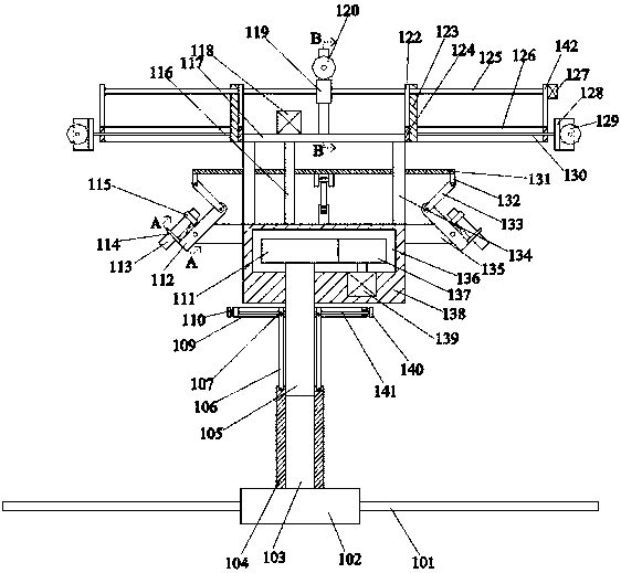
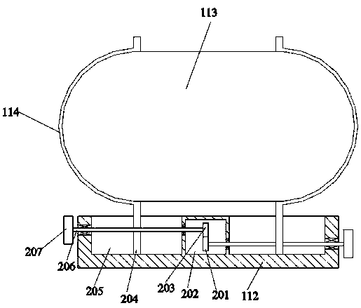
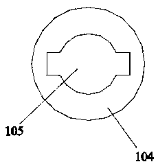
[0022] Such as Figure 1-Figure 4As shown, the present invention is described in detail. For the convenience of description, the orientations mentioned below are now stipulated as follows: figure 1 The up, down, left, right, front and back directions of the projection relationship are the same. A desulfurization and denitrification supporting equipment of the present invention includes a bottom box 138. A rotary cleaning device for cleaning by rotating is arranged under the bottom box 138. The upper side of the rotary cleaning device is arranged There is a solvent spraying device positioned on the upper end surface of the bottom case 138 and spraying cleaning solvent, above the solvent spraying device is provided with a rolling device that is fixed to the bottom case 138 and facilitates the stable movement of this equipment and the equipment to be cleaned, Thus, the above device is used to realize efficient cleaning of the reactor in the desulfurization and denitrification equ...


PUM


Abstract

The invention discloses desulfurization and denitrification associated equipment. The desulfurization and denitrification associated equipment comprises a bottom box. A rotary cleaning device capableof rotating to implement cleaning is arranged below the bottom box. A solvent spraying device located on the upper end face of the bottom box and used for spraying out a cleaning solvent is arranged on the upper side of the rotary cleaning device. A rolling device is arranged above the solvent spraying device, and the rolling device is fixed to the bottom box and can be stably matched with a device to be cleaned to move. The desulfurization and denitrification associated equipment is simple in structure. Through the rotary cleaning device, the solvent spraying device and the rolling device, the equipment operates in cooperation with a hoisting device in an external space and a cleaning fluid supply device, a reaction kettle in desulfurization and denitrification equipment is cleaned efficiently, the working efficiency of the equipment is improved, and the cleaning difficulty is reduced. Moreover, a brushing structure in the equipment can be changed through multiple cleaning fluid spraying angle adjustment modes so that impurities in the reaction kettle can be cleaned better.

Description

technical field [0001] The invention relates to the technical field of desulfurization and denitrification equipment, in particular to a desulfurization and denitrification supporting equipment. Background technique [0002] When the desulfurization and denitrification equipment is working, it often involves some chemical solvents to neutralize the sulfide and nitrate in the smoke. In this process, some supporting equipment is used, such as: a reaction kettle for chemical neutralization reaction. When the equipment is working, it adopts a closed box space, and the manufacture of the reactor is made of anti-corrosion metal products. Some stubborn impurities will be generated, which will reduce the service life of the reactor, reduce the structural stability of the equipment, greatly affect the practical safety of the equipment, and make the reaction efficiency of the equipment low when it is working, which greatly reduces the equipment's safety. Production efficiency, and th...

Claims


Application Information

Patent Timeline
IPC IPC(8): B08B9/093
CPCB08B9/093
Inventor 胡月明
Owner 胡月明
Why Eureka
Try Eureka