Electrical circuit current detection method based on magnetometer sensor

A magnetic sensor and line current technology, applied in the direction of only measuring current, measuring current/voltage, instruments, etc., can solve problems such as circuit damage, difficulty in detecting the magnitude of the electric current, and difficulty in overall shielding, so as to ensure measurement accuracy , Conducive to mass production, save the effect of installation steps

Pending Publication Date: 2019-08-13
HEFEI KDLIAN SAFETY TECHNOLOGY CO LTD +2
View PDF0 Cites 5 Cited by
  • Summary
  • Abstract
  • Description
  • Claims
  • Application Information

AI Technical Summary

Problems solved by technology

The four devices are usually independent, and the external power-taking device may be independent, or may be embedded in the monitoring detector and the IoT communication module respectively. The entire system is generally installed in the power distribution cabinet. However, this monitoring method exists as follows Defects: First, when installing the monitoring equipment, it is necessary to disconnect the line and pass the tested cable into the coil of the residual current transformer, resulting in damage to the original circuit or temporary changes, which is not conducive to the renovation of old buildings
Second, this method can usually only be used to detect the residual current, that is, the magnitude of the leakage, but it is difficult to detect the magnitude of the power current, which is not conducive to discovering accidents and hidden dangers caused by local overcurrent
Third, this method usually cannot accurately fix the relative position between the coil and the cable, resulting in low measurement accuracy
Fourth, this method leads to the fact that the detection coil cannot be made very small, and there are many components, low integration, and it is difficult to shield as a whole. The fineness and placement density are not conducive to the accurate diagnosis of electrical circuits, and it is even more difficult to use it in temporary places where electricity is used.

Method used


Image

  • Electrical circuit current detection method based on magnetometer sensor
  • Electrical circuit current detection method based on magnetometer sensor
  • Electrical circuit current detection method based on magnetometer sensor

Examples


Embodiment 1

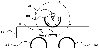
[0027] An example of current detection of a single cable circuit using the method described in this patent is image 3 shown. Method The device is attached to the cable under test 211 through the upper fixing device 161 without disconnecting the cable under test 211 . The lower left fixing device 162 and the lower right fixing device 163 do not need to be connected and can be left empty. Current I in the tested cable 211 311 The direction flows into the paper, according to Ampere's law, the current I 311 A circumferentially distributed induced magnetic field will be formed around the cable 211, including the magnetic field B falling on the magnetic sensor 11 311 strength. The magnetic sensor should have at least one sensitive axis, and there should be one sensitive axis and magnetic field B 311 The magnetic induction is parallel. Thus, the magnetic field B 311 Can be measured by the magnetic sensor 11, forming a magnetic field B 311 The magnetic induction intensity is ...

Embodiment 2

[0029] The implementation example of using the method described in this patent to monitor the current of the live line and neutral line cable of single-phase AC mains power Figure 4 shown. Method The device is attached to a pair of tested live wire 222 and neutral wire 223 cables through the left lower fixing device 162 and the right lower fixing device 163. Typically, the left lower fixing device 162 is attached to the live wire 222 cable, and the right The lower fixing device 163 is attached to the neutral line 223 cable, and the upper fixing device 161 does not need to be installed and can be left empty. Current in live wire 222 cable and neutral current in 223 cable The directions flow into and out of the paper respectively, they are alternating currents with the same frequency and phase, and the amplitude can be expressed as:

[0030]

[0031]

[0032] where w is the frequency of the alternating current and t is the time.

[0033] According to Ampere's law, t...

Embodiment 3

[0055] Examples of using the method described in this patent to detect the current of a three-phase AC line are Image 6 shown. The intelligent microsystem is attached to the three phase lines of a group of three-phase lines through the upper fixing device 161 , the lower left fixing device 162 and the lower right fixing device 163 . According to the solution of this patent, the centers of the upper fixing device 161, the lower left fixing device 162, and the lower right fixing device 163 in the vertical section are equilateral triangles, and the geometric center is located at the center of the magnetic sensor 11. There are two sensitive axes, and there is no restriction on the direction of the axes. Typically, the upper fixing device is attached to the phase A cable 231 , the fixing device 162 is attached to the phase B cable 232 , and the fixing device 163 is attached to the phase C cable 233 . Current in A-phase cable 231 , B-phase cable 232 and C-phase cable 233 with ...


PUM


Abstract

The invention discloses an electrical circuit current detection method based on a magnetometer sensor. The magnetometer sensor, a microcontroller, a radio frequency transceiver, a system-level package, a fixing device and a power supply unit are provided; the non-access type monitoring can work by only adopting an external adherent fixing way without changing a tested circuit; the current is indirectly measured by utilizing a magnetic measurement method, the electric leakage can be monitored, and the electro-current size can be analyzed; through the method disclosed by the invention, the structure is compact, so that the required equipment is small in volume, light in weight, less in module, simple in structure and incapable of causing additional space and weight burden, and a mounting step of interconnecting debugging modules is saved; the mounting precision is high, and the measurement accuracy is ensured; the equipment power consumption is greatly reduced, the power supply is flexible, the equipment can stably work for a long time, and especially suitable for the temporary electricity utilization or mobile electricity utilization occasion; the whole product adopts the system-level package technology, and is in favor of batch production and capable of reducing the cost.

Description

technical field [0001] The invention relates to the technical fields of active component circuits, passive component circuits, modulation, demodulation, amplifiers, amplification control, pulses, encoding, etc., and in particular to a method for detecting electric circuit current based on a magnetic sensor. Background technique [0002] Electric energy is the most important secondary energy and plays an important basic role in production and life. With the substantial increase in electricity consumption, electrical safety accidents such as electrical fires and personal electric shocks also occur frequently, seriously endangering life and property safety. In these accidents, electrical circuit leakage and local excessive current are the main causes, so real-time online monitoring of current is very important. Such as Figure 8 , At present, the methods for online detection of line current on the market are mainly based on residual current transformers, and the matching tempe...

Claims


Application Information

Patent Timeline
Patent Type & Authority Applications(China)
IPC IPC(8): G01R19/00
CPCG01R19/0092
Inventor 袁宏永尤睿鲁文帅苏国锋周扬
Owner HEFEI KDLIAN SAFETY TECHNOLOGY CO LTD
Why Eureka
Try Eureka