Stainless steel flange

A stainless steel and flange technology, applied in flange connection, by detecting the appearance of fluid at the leak point, pipe/pipe joint/pipe fitting, etc., it can solve the problems of external pipe damage, poor sealing, complicated installation and disassembly, etc. , to achieve the effect of less damage, ensuring sealing and increasing safety performance

Active Publication Date: 2019-08-09
常州大谷液压器材有限公司
View PDF6 Cites 2 Cited by
  • Summary
  • Abstract
  • Description
  • Claims
  • Application Information

AI Technical Summary

Problems solved by technology

[0003] However, when the traditional stainless steel flanges on the market are connected with the external pipe fittings, they are fixed with fixed snap rings, which will inevitably cause damage to the outer wall of the external pipe, resulting in the service life of the external pipe cannot be guaranteed, and installation and The disassembly is more complicated and the sealing is not strong: at the same time, when the stainless steel flange is connected with the external pipe used for gas transportation, the airtightness of the flange during the working process cannot be effectively detected, and the safety cannot be guaranteed

Method used


Image

  • Stainless steel flange
  • Stainless steel flange
  • Stainless steel flange

Examples


Embodiment Construction

[0023] The embodiments of the present invention will be described in detail below with reference to the accompanying drawings, but the present invention can be implemented in many different ways defined and covered by the claims.

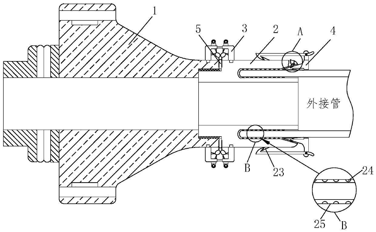
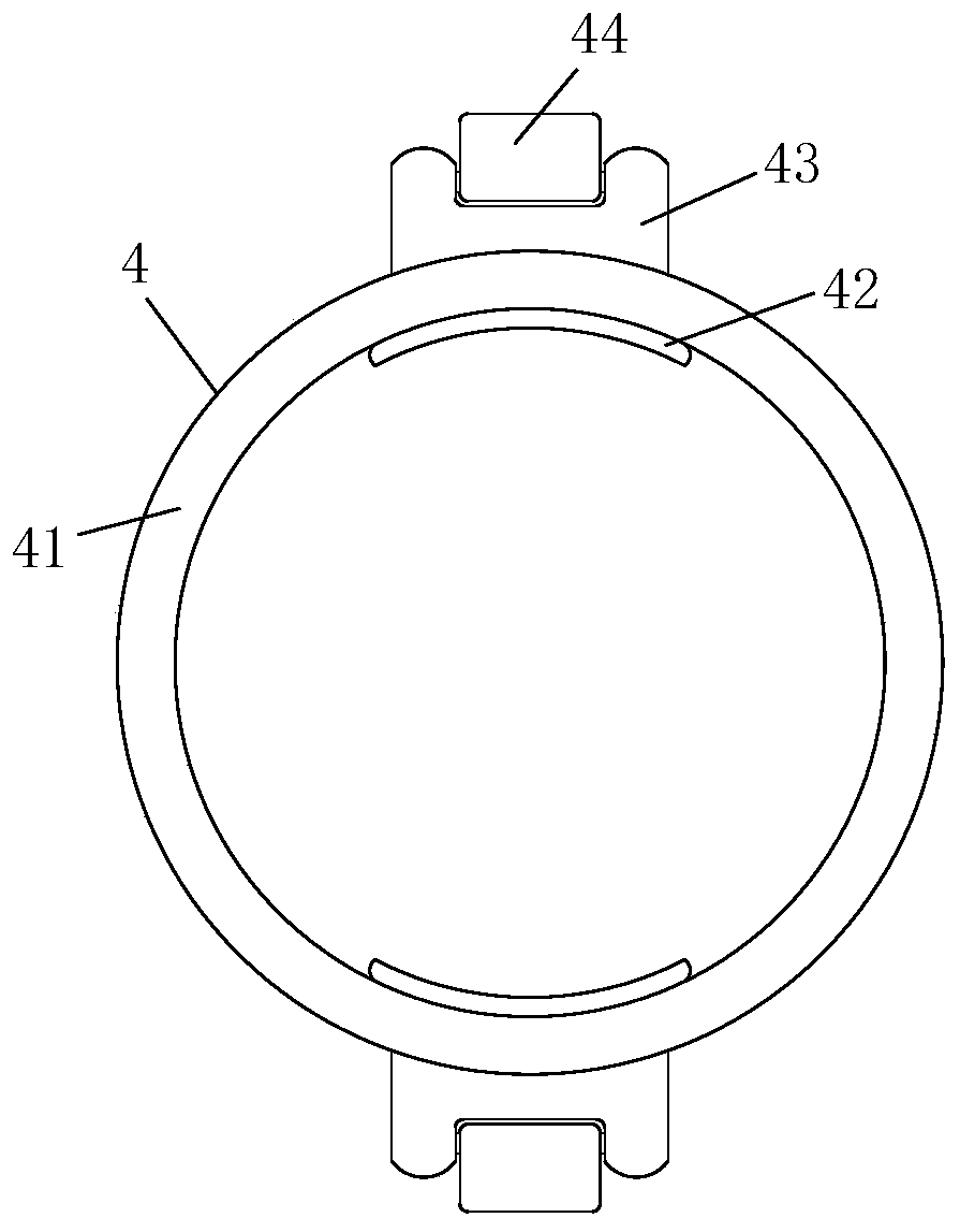
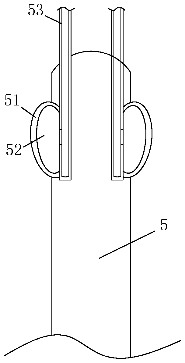
[0024] Such as Figure 1-6 As shown, a stainless steel flange includes a flange main body 1, a connecting end 2, a detection component 3, a sealing component 4 and a silicone gasket 5, and one end of the flange main body 1 is threadedly connected to a connecting end 2, A silicone gasket 5 is installed at the joint between the connecting end 2 and the flange main body 1, and a detection component 3 is installed on the outer side of the silicone gasket 5, and a sealing component 4 is connected to the end of the connecting terminal 2;

[0025] The connection terminal 2 includes a block 21, a driving rope 22, a triangular limit block 23, a rubber ball 24 and a socket 25. One end of the connection terminal 2 is provided with a socket 25, and the two sock...


PUM


Abstract

The invention relates to a stainless steel flange which comprises a flange body, a connecting end, a detection assembly, a sealing assembly and a silica gel sealing gasket. One end of the flange bodyis in threaded connection with the connecting end. The silica gel sealing gasket is mounted at the joint of the connecting end and the flange body. The detection assembly is mounted on the outer sideof the silica gel sealing gasket. The tail end of the connecting end is connected with the sealing assembly. The connecting end comprises a clamp block, a drive rope, a triangular limiting block, rubber balls and an inserted connection groove. The inserted connection groove is formed in one end of the connecting end. The rubber balls are evenly embedded to the inner walls of the two sides of the inserted connection groove. One side of the top end of the inserted connection groove is movably connected with the clamp block through a first rotating shaft, and a first torsional spring is arrangedat the joint of the clamp block and the first rotating shaft. Through cooperation between the connecting end and the sealing assembly, connection between external pipes can be completed rapidly and conveniently, device air tightness can be detected and controlled in real time through the detection assembly and other components, and safety performance is high.

Description

technical field [0001] The invention relates to the technical field of pipeline engineering equipment, in particular to a stainless steel flange. Background technique [0002] Flange is a disc-shaped part, which is the most common in pipeline engineering. Flanges are used in pairs and with matching flanges on valves. In pipeline manufacturing, Flanges are mainly used for the link of pipelines. The flange connection is easy to use and can withstand greater pressure. In industrial pipelines, flange connections are also widely used. The stainless steel flange is one of many flanges. [0003] However, when the traditional stainless steel flanges on the market are connected with the external pipe fittings, they are fixed with fixed snap rings, which will inevitably cause damage to the outer wall of the external pipe, resulting in the service life of the external pipe cannot be guaranteed, and installation and The disassembly is more complicated and the sealing is not strong: ...

Claims


Application Information

Patent Timeline
Patent Type & Authority Applications(China)
IPC IPC(8): F16L23/024F16L23/22G01M3/04
CPCF16L23/024F16L23/22G01M3/04
Inventor 许吉界付子豪高亚芳
Owner 常州大谷液压器材有限公司
Why Eureka
Try Eureka