
Feed pressure assembly for ultrasonic plasticizing system

A component and feeding technology, applied in the field of feeding pressure components for ultrasonic plasticizing systems, can solve the problem of shortening the service life of the ultrasonic vibration system and the ultrasonic tool head, overheating and overloading of the ultrasonic vibration system, and wear of the barrel parts. Ultrasonic energy and other problems, to achieve the effect of reducing manual feeding time and simple and compact structure

Active Publication Date: 2022-03-11
CENT SOUTH UNIV
View PDF7 Cites 0 Cited by
  • Summary
  • Abstract
  • Description
  • Claims
  • Application Information

AI Technical Summary

Problems solved by technology

[0003] Although the ultrasonic plasticizing equipment has solved the above problems to a certain extent, there are still some defects, such as no automatic quantitative feeding device, resulting in particle splashing during the polymer filling process, no rough metering step before plasticizing, The amount of plasticization is not well estimated; the ultrasonic tool head has both plasticization and melt transportation, and the method is simple without considering the severe friction between the ultrasonic tool head and the barrel wall under the condition of high-frequency vibration, resulting in the ultrasonic tool head and barrel parts The rapid wear and loss of ultrasonic energy further cause the ultrasonic vibration system to overheat and overload, which greatly shortens the service life of the ultrasonic vibration system and the ultrasonic tool head, and the use and maintenance costs of the ultrasonic plasticizing system are relatively high

Method used


Image

  • Feed pressure assembly for ultrasonic plasticizing system
  • Feed pressure assembly for ultrasonic plasticizing system
  • Feed pressure assembly for ultrasonic plasticizing system

Examples


Embodiment Construction

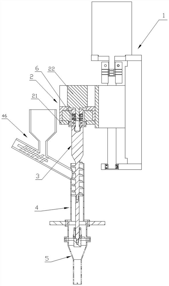
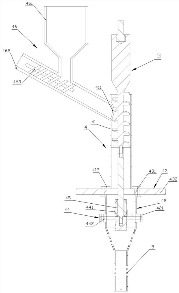
[0034] like figure 1 As shown, the ultrasonic plasticizing system provided by the present invention uses a feed pressure assembly, which includes a translation mechanism 1, a rotation mechanism 2, a feed pressure assembly 3 and a barrel assembly 4, wherein the translation mechanism 1 is a wire The bar slide table, the rotating mechanism 2 is connected on the sliding table, the feed pressing assembly 3 is connected with the rotating mechanism 2, and the bottom end of the feeding pressing assembly passes through the barrel assembly 4 and extends into the plasticizing chamber 5.

[0035] like figure 1 As shown, the rotating mechanism 2 includes a motor base 21 and a stepping motor 22. The motor base 21 is a rectangular seat with an open top, and its bottom end is provided with a through hole. The stepping motor 22 is assembled in the motor base, and the output shaft of the stepping motor After passing through the through hole, it is connected with the feeding pressure assembly 3...


PUM


Abstract

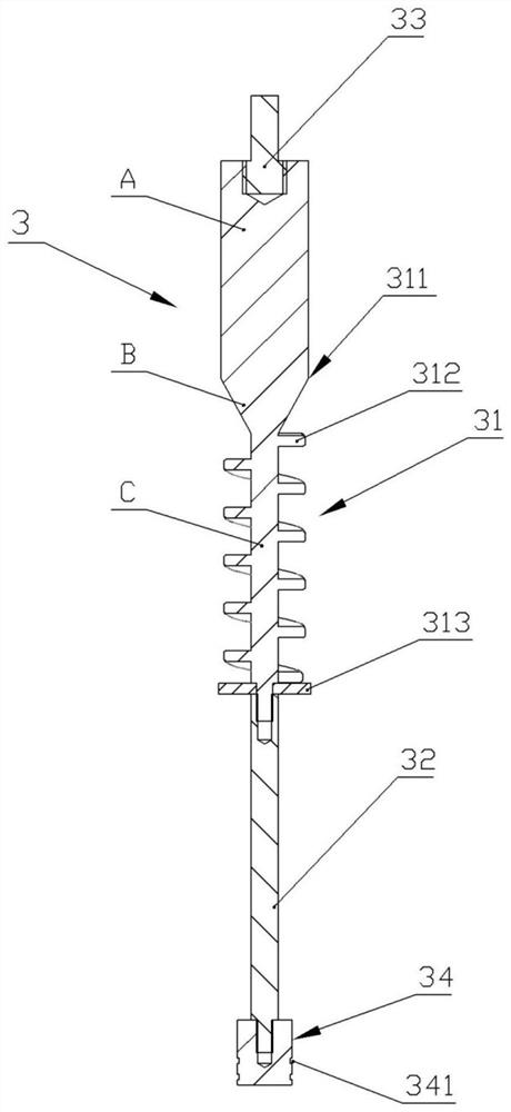
The invention discloses a feeding and pressing assembly for an ultrasonic plasticizing system, which includes a translation mechanism, a rotating mechanism, a feeding and pressing assembly and a barrel assembly; the feeding and pressing assembly includes a quantitative delivery rod, a transition rod, a connection Shaft and pressure plunger, one end of the quantitative delivery rod is connected with the pressure plunger through a transition rod, and the other end is connected with the connecting shaft; the barrel assembly includes a barrel, the side wall of the barrel is provided with a feed port, the feed The pressure exerting component is placed in the material cylinder and connected with the rotating mechanism through a connecting shaft, and the pressure applying plunger passes through the material cylinder and extends into the plasticizing chamber; the rotating mechanism is connected with the translation mechanism. The polymer particles are buffered on the quantitative conveying rod, the rotating mechanism works, the polymer particles move downward quantitatively, realizing quantitative feeding, reducing the manual feeding time and predicting the delivery of the required materials, realizing continuous automatic production; then the translation mechanism drives the feeding The material pressure component goes down to provide plasticizing pressure. After plasticizing, the melt enters the injection unit to realize the integration of quantitative feeding and conveying.

Description

technical field [0001] The invention belongs to the field of ultrasonic plasticizing molding, in particular to a feeding pressure component for an ultrasonic plasticizing system. Background technique [0002] At present, micro-nano parts have been widely used in many fields such as aerospace, military, and automobile industries. Micro-injection molding technology is a typical representative of micro-nano manufacturing technology. Micro-molding technology, polymer micro-injection molding has the advantages of low cost, batch production, and high precision. However, the traditional micro-injection molding technology has problems such as long plasticization time, excessive plasticization volume at one time, serious mismatch between injection volume and micro-part volume, etc., resulting in poor stability of molding quality and serious waste of raw materials. To solve these problems, technicians have developed ultrasonic plasticizing equipment. [0003] Although the ultrasonic...

Claims


Application Information

Patent Timeline
Patent Type & Authority Patents(China)
IPC IPC(8): B29C45/18B29C45/62B29C45/46B29C45/53
CPCB29C45/18B29C45/1808B29C45/62B29C45/46B29C45/53B29C2945/76183B29C2945/76351
Inventor 吴旺青强元宝蒋炳炎
Owner CENT SOUTH UNIV
Learn More