Anti-blocking negative-pressure flushing drainage device

A negative pressure and anti-blocking technology, which is applied in the direction of suction equipment, suction and irrigation systems, etc., can solve the problems of continuous unobstructed drainage, easy blockage of drainage tubes, and increased mortality of patients, so as to promote infection control and improve treatment effect , to avoid the effect of pipeline collapse

Inactive Publication Date: 2019-08-09
吴绍宏
View PDF11 Cites 1 Cited by
  • Summary
  • Abstract
  • Description
  • Claims
  • Application Information

AI Technical Summary

Problems solved by technology

[0003] When flushing, drainage, support, etc. are carried out at the same time, it is often necessary to place multiple drainage tubes, and sometimes it is even necessary to open multiple drainage ports or to perform repeated operations to remove necrosis or infection, which also brings pain to the patient and increases the mortality rate of the patient. and cause serious economic and social burdens
[0004] Due to the simple structure of the single-chamber drainage tube, a variety of flushable multi-chamber drainage tubes have appeared at present, but when the drainage tube in the prior art is used to perform negative pressure drainage on the deep tissue of the patient, the patient will suffer under the effect of negative pressure. Deep necrotic tissue, blood clots, omentum, intestinal tube and soft tissue are still very easy to block the drainage tube, and the effect of continuous unobstructed drainage is still not achieved, which has always been a difficult problem for clinicians

Method used


Image

  • Anti-blocking negative-pressure flushing drainage device
  • Anti-blocking negative-pressure flushing drainage device
  • Anti-blocking negative-pressure flushing drainage device

Examples


Embodiment Construction

[0035] The preferred embodiments of the present invention are given below in conjunction with the accompanying drawings to describe the technical solution of the present invention in detail.

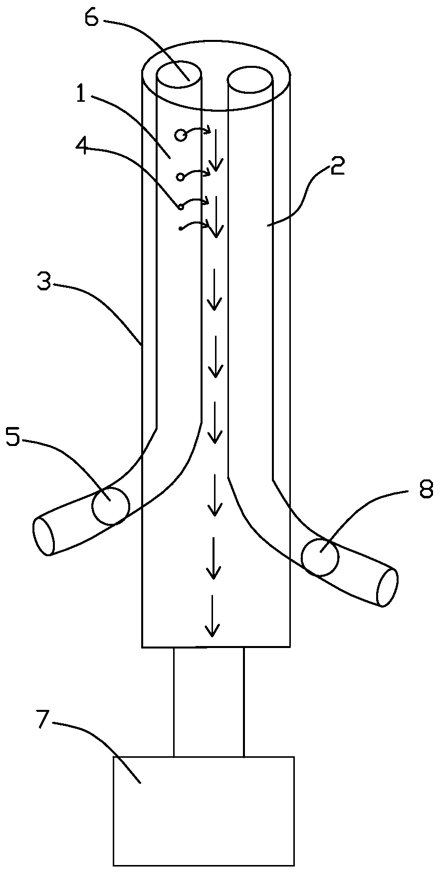
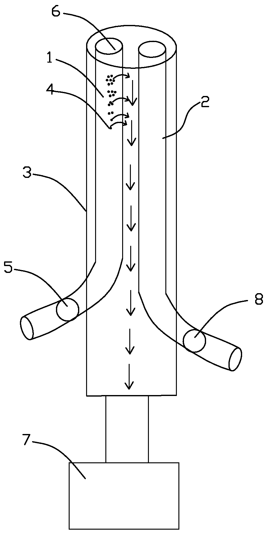
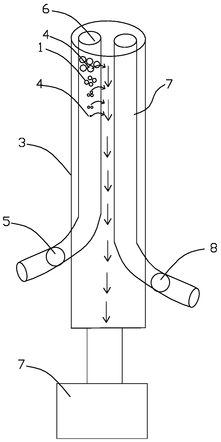
[0036] figure 1 It is a schematic diagram of the overall structure of one of the embodiments of the present invention, figure 2 It is a schematic diagram of the overall structure of Embodiment 2 of the present invention, image 3 It is a schematic diagram of the overall structure of Embodiment 3 of the present invention. Such as figure 1 , 2 , 3: the anti-blocking negative pressure flushing and drainage device provided by the present invention, the anti-blocking negative pressure flushing and drainage device is used to indwell and drain the effusion in the deep tissue of patients during or after surgery, and the anti-blocking negative pressure flushing and drainage device Including: two small tubes and one large tube 3; parts of the two small tubes are sleeved in the large tube 3, a...


PUM


Abstract

The invention relates to an anti-blocking negative-pressure flushing drainage device. The device is used for storing hydrops drained into the deep tissue of patients during or after surgery, and comprises two small tubes and one large tube. The large tube is a hydrops leading-out tube, the first small tube is a gas leading-in tube, and the second small tube is a flushing liquid leading-in tube; one end of the large tube is provided with an opening for sucking hydrops, and the other end of the large tube is connected with a negative-pressure pump; one small tube is provided with a row of vent holes for balancing pressure, and in the direction from the negative-pressure pump to a suction port of the small tube, the diameters of the vent holes are successively increased or the diameters remain unchanged but the number of the vent holes is gradually increased or the diameters are successively increased and the number of the vent holes is gradually increased. The device is used for drainingand flushing the deep tissue of an affected part to realize continuous or intermittent low-negative-pressure suction. In addition, sterile gas and liquid are used for continuously or alternatively flushing a pipeline, and the device has the advantages of preventing collapse, wall sticking and blockage of the pipeline, achieving the purpose of continuous normal drainage, completely draining infection lesions, promoting infection control, improving the comfort of the patients, reducing the treatment cost and the like.

Description

technical field [0001] The invention relates to a drainage device, in particular to an anti-blocking negative pressure flushing and drainage device for drainage and flushing of deep tissues of an affected part, which is beneficial to improving the therapeutic effect of negative pressure drainage and flushing. Background technique [0002] The purpose of surgical drainage is to guide the pus, blood, and liquid abnormal substances accumulated between human tissues or body cavities, including pus, hemorrhage, or necrotic tissue, to the outside of the body, so as to prevent and treat infection and promote tissue healing. There are many types of surgical drainage tubes used clinically, and they are widely used in the drainage of wounds, chest cavity, brain cavity, gastrointestinal tract, biliary tract, abscess, etc., and are an important measure for clinical treatment of diseases. Unsmooth drainage often leads to accumulation of pus, blood, and fluid in the body, secondary seriou...

Claims


Application Information

Patent Timeline
Patent Type & Authority Applications(China)
IPC IPC(8): A61M1/00
CPCA61M1/0058
Inventor 吴绍宏王瑞兰洪江田锐金卫
Owner 吴绍宏
Why Eureka
Try Eureka