Three-level Boost converter, control method and photovoltaic system
A converter and three-level technology, applied in the direction of inductors, photovoltaic modules, photovoltaic power generation, etc., can solve the problems of inconsistent magnetic core saturation, unbalanced bus capacitance, reduce the cost, volume and weight of the converter, and achieve improved Reliability, reducing inductor current ripple, and avoiding the effect of bus capacitor uneven voltage
- Summary
- Abstract
- Description
- Claims
- Application Information
AI Technical Summary
Problems solved by technology
Method used
Image
Examples
Embodiment 1
[0063] Embodiment 1 of the present application provides a three-level Boost converter, which will be described in detail below with reference to the accompanying drawings.
[0064] see Figure 5 , which is a schematic diagram of a three-level Boost converter provided in Embodiment 1 of the present application.
[0065] The converter includes: an integrated coupling reactance 501 , a first switch tube Q1 , a second switch tube Q2 , a third switch tube Q3 and a fourth switch tube Q4 , a first capacitor C1 and a second capacitor C2 . Wherein, the integrated coupling reactance 501 includes a first winding N1, a second winding N2 and a common magnetic core, and the first winding N1 and the second winding N2 share the common magnetic core.
[0066] The first end of the first winding N1 is connected to the positive input end of the converter, the second end of the first winding N1 is connected to the first node A, the first end of the third switching transistor Q3 is connected to th...
Embodiment 2
[0079] Embodiment 2 of the present application also provides another three-level Boost converter, which is different from Embodiment 1 in that the first winding and the second winding of the three-level Boost converter provided in this embodiment have the same inductance. In order to realize the simultaneous turn-on or turn-off of the first switch tube and the second switch tube, the converter also includes an isolation drive chip, which will be described in detail below with reference to the accompanying drawings.
[0080] see Figure 7 , which is a circuit diagram of another three-level Boost converter provided in Embodiment 2 of the present application.
[0081] Based on the converter provided in Embodiment 1, the converter provided in this embodiment further includes: a first isolation driver chip 701 and a second isolation driver chip 702 . The first isolation driver chip 701 and the second isolation driver chip 702 may be identical.
[0082] The first switching tube Q1...
Embodiment 3
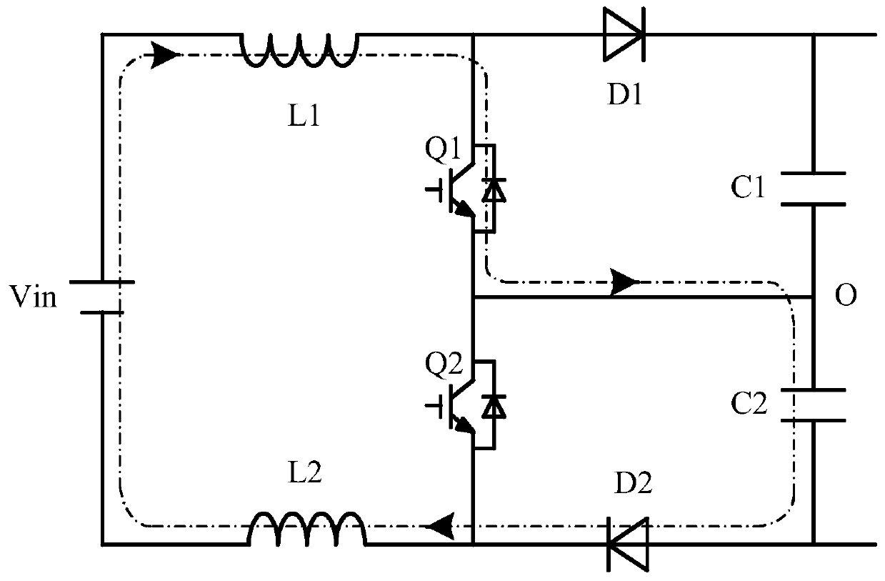
[0090] continue to see Figure 2 to Figure 4 , due to the asynchronous three-level control method used in the control of the traditional three-level Boost converter, the potential of the midpoint O of the output bus capacitor has a large common-mode voltage jump relative to the negative input terminal, which increases the leakage current ; and the inductor current flows through C2 when Q1 is turned on and Q2 is turned off, and flows through C1 when Q1 is turned off and Q2 is turned on. The charging time of C1 and C2 is inconsistent, so it is necessary to add additional voltage equalization control to balance the voltage of C1 and C2 , leading to complex system control. In order to solve the above problems, an embodiment of the present application further provides a method for controlling a three-level Boost converter, which will be described in detail below with reference to the accompanying drawings.
[0091] The control method provided in the embodiment of this application ...
PUM
 Abstract
Description
Claims
Application Information
 - R&D
- Intellectual Property
- Life Sciences
- Materials
- Tech Scout
- Unparalleled Data Quality
- Higher Quality Content
- 60% Fewer Hallucinations
Browse by: Latest US Patents, China's latest patents, Technical Efficacy Thesaurus, Application Domain, Technology Topic, Popular Technical Reports.
© 2025 PatSnap. All rights reserved.Legal|Privacy policy|Modern Slavery Act Transparency Statement|Sitemap|About US| Contact US: help@patsnap.com


