
Laser light source reflective sighting telescope

A laser light source, reflective technology, applied in the field of sights, can solve problems such as interference aiming, and achieve the effect of flexible use and low loss

Pending Publication Date: 2019-08-06
NANTONG JULANG OPTOELECTRONICS TECH CO LTD
View PDF0 Cites 0 Cited by
  • Summary
  • Abstract
  • Description
  • Claims
  • Application Information

AI Technical Summary

Problems solved by technology

[0007] If the laser is directly placed in the inner tube lamp holder, the laser is directly irradiated on the reflector, and the light utilization rate is high, but due to the laser emitting crystal, the shape of the emission is a rectangle instead of a conventional dot, assuming Add an aperture in front of the laser, because the aperture is very small, it will cause the laser to diffract, the point of observation is a bright and dark feeling, which interferes with the aiming

Method used


Image

  • Laser light source reflective sighting telescope
  • Laser light source reflective sighting telescope
  • Laser light source reflective sighting telescope

Examples


Embodiment Construction

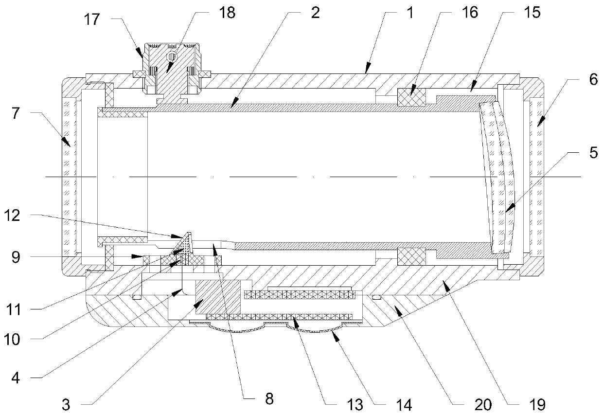
[0026] Such as figure 1 As shown, a laser light source reflective sight includes a mirror body 1 , an inner tube 2 , a laser 3 , an optical fiber 4 and a concave reflector 5 . The inside of the mirror body 1 is a cavity structure, and the front and rear end surfaces of the mirror body 1 are respectively equipped with a front protective glass 6 and a rear protective glass 7. The laser 3 and the optical fiber 4 are installed in the mirror body 1. The laser 3 and the optical fiber 4 coupling connection. The inner tube 2 is horizontally installed in the mirror body 1 , and the front end of the inner tube 2 is fixedly mounted with a concave reflector 5 , and the concave reflector 5 is arranged obliquely relative to the axis of the inner tube 2 . There is a light transmission hole 8 on the peripheral wall of the inner tube 2, and an optical fiber holder 9 is installed at the light transmission hole 8 in the mirror body 1, and an optical fiber support ring 10 is fixedly installed in...


PUM


Abstract

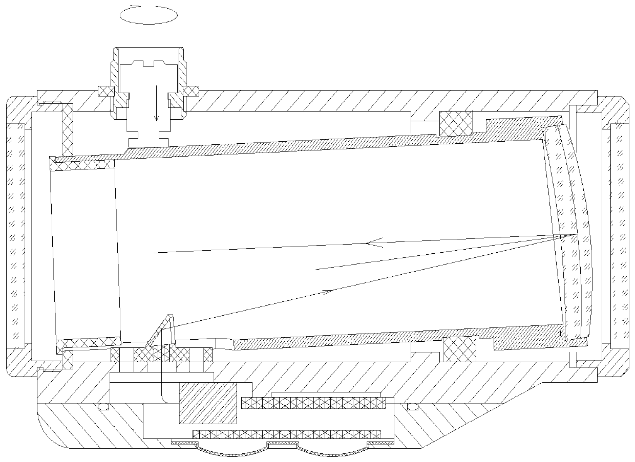
The invention provides a laser light source reflective sighting telescope which comprises a telescope body, an inner pipe, a laser, an optical fiber and a concave reflecting mirror. Front protective glass and back protective glass are fixed onto the front end surface and the back end surface of the telescope body; the laser and the optical fiber are arranged in the telescope body and are in coupled connection; the inner pipe is arranged in the telescope body; the concave reflecting mirror is arranged at the front end of the inner pipe and is inclinedly arranged relative to the axis of the inner pipe; a light transmitting hole is formed in the circumferential wall of the inner pipe; an optical fiber seat is arranged at the position, located at the light transmitting hole, in the telescope body; an optical fiber support ring is fixed into the optical fiber seat; the tail end of the optical fiber penetrates through the optical fiber support ring along the radial direction of the inner pipe; the tail end of the optical fiber is located on a focal plane of the concave reflecting mirror; an emergent ray of the optical fiber penetrates through the light transmitting hole; an included angle is formed between the emergent ray of the optical fiber and a main optical axis of the concave reflecting mirror; and a laser light can be reflected out of the telescope body from the back protective glass through the concave reflecting mirror. According to the laser light source reflective sighting telescope provided by the invention, a laser diffraction phenomenon of the sighting telescope canbe improved, and sighting cannot be interfered.

Description

technical field [0001] The invention belongs to the technical field of sights, and in particular relates to a laser light source reflective sight. Background technique [0002] Reflex sights, also known as red dots, are optical sights without magnification. Reflective sights use the principle of spherical reflection to make the reflected light incident on the eyes parallel to the observer's eyes, so that the observer's eyes can see the red dot without having to be on the central axis of the lens, which can improve the moving target or body movement. shooting accuracy. The light source part of the reflective sight currently includes LED light source, isotope radiation light source, natural light source and so on. [0003] The isotope radiation source uses the visible light radiated by a radioactive element as the light source, which is characterized by a very long life, but the disadvantage is that the cost is relatively high. [0004] Natural light is a light hole that gu...

Claims


Application Information

Patent Timeline
Patent Type & Authority Applications(China)
IPC IPC(8): F41G1/30
CPCF41G1/30
Inventor 李越
Owner NANTONG JULANG OPTOELECTRONICS TECH CO LTD
Learn More