
Method for preparing antireflection grating

An anti-reflection and grating technology, which is applied in the direction of diffraction grating, optical mechanical equipment, photoplate making process of patterned surface, etc., to achieve the effect of wide application value, clear physical meaning and high precision

Inactive Publication Date: 2010-08-18
SHANGHAI INST OF OPTICS & FINE MECHANICS CHINESE ACAD OF SCI
View PDF4 Cites 2 Cited by
  • Summary
  • Abstract
  • Description
  • Claims
  • Application Information

AI Technical Summary

Problems solved by technology

But to the best of our knowledge, no one has proposed a method for designing antireflective periodic structures using the concept of mode refractivity in mode theory

Method used


Image

  • Method for preparing antireflection grating
  • Method for preparing antireflection grating
  • Method for preparing antireflection grating

Examples


Embodiment Construction

[0031] The present invention will be further described below in conjunction with the embodiments and accompanying drawings, but the protection scope of the present invention should not be limited thereby.

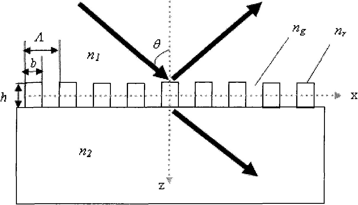
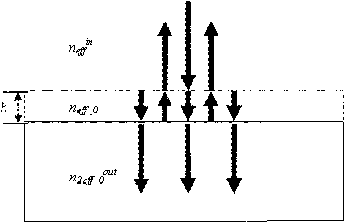
[0032] see first figure 1 and figure 2 , figure 1 It is a schematic diagram of the geometric structure of the anti-reflection grating of the present invention. figure 2 yes figure 1 Schematic diagram of the equivalent structure of an anti-reflection grating. figure 1 In , regions 1 and 2 are homogeneous, which are incident medium and grating substrate material respectively. The vibration direction of the TE polarized incident light corresponding to the electric field vector is perpendicular to the incident plane, and the vibration direction of the TM polarized incident light corresponding to the magnetic field vector is perpendicular to the incident plane. The linearly polarized light wave is incident at a certain angle θ, λ represents the incident wavelength, and Λ ...


PUM

PropertyMeasurementUnit
depthaaaaaaaaaa

Abstract

The invention provides a method for preparing an antireflection grating. The method ensures that the antireflection grating is equivalent to a simple Fabry-Perot interferometer structure by using the concept of effective mode-index in a pattern theory. The method comprises the following three steps: (1) selecting a corresponding grating substrate material, an incident wavelength, an incident angle, refractive index of an incident medium and an incident mode according to requirements; (2) allowing a prepared one-dimensional rectangular grating to be equivalent to a structure similar to an F-P cavity, calculating the incident medium, the grating region and the effective refractive index of the incident medium according to the pattern theory; and (3) preparing the antireflection grating by adopting a photoetching method according to the antireflection grating parameters. The method has the characteristics of high accuracy and clear physical significance, and has important application value in the aspects of designing and preparing the antireflection grating.

Description

technical field [0001] This patent relates to an anti-reflection grating, especially a preparation method of an anti-reflection grating. Background technique [0002] Anti-reflective surfaces are used in a wide range of modern optical technologies, such as solar cells, electro-optic devices and sensors. Using thin films to make such antireflective structures is a common method, but some difficult problems are often encountered in thin film technology, including: thermal expansion mismatch, adhesion, and film stability. On the other hand, studies have shown that optical surfaces with anti-reflection properties can also be fabricated by using high-density periodic structure-subwavelength gratings. Since the antireflective structure is produced by etching on the same substrate material, the above-mentioned problems encountered in thin film technology do not exist in this periodic structure. So far, the method used to design such an anti-reflection periodic structure is mainly...

Claims


Application Information

Patent Timeline
Patent Type & Authority Applications(China)
IPC IPC(8): G02B5/18G03F7/00
Inventor 周常河曹红超冯吉军
Owner SHANGHAI INST OF OPTICS & FINE MECHANICS CHINESE ACAD OF SCI
Learn More