Material control type drainage valve
A technology of relief valve and valve body, applied in the field of relief valve, can solve the problems of low practicability, large water output, single structure, etc., and achieve the effect of avoiding excessive water output
- Summary
- Abstract
- Description
- Claims
- Application Information
AI Technical Summary
Problems solved by technology
Method used
Image

Examples
Embodiment 1
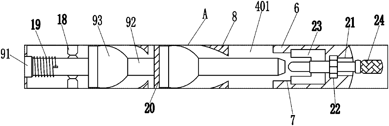
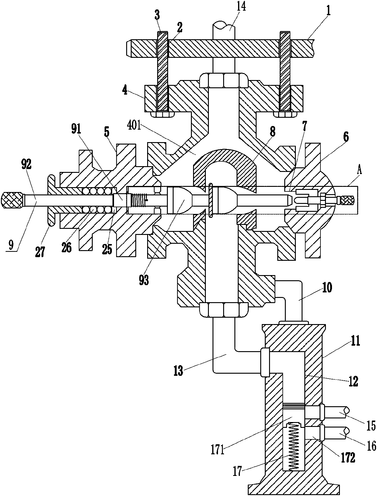
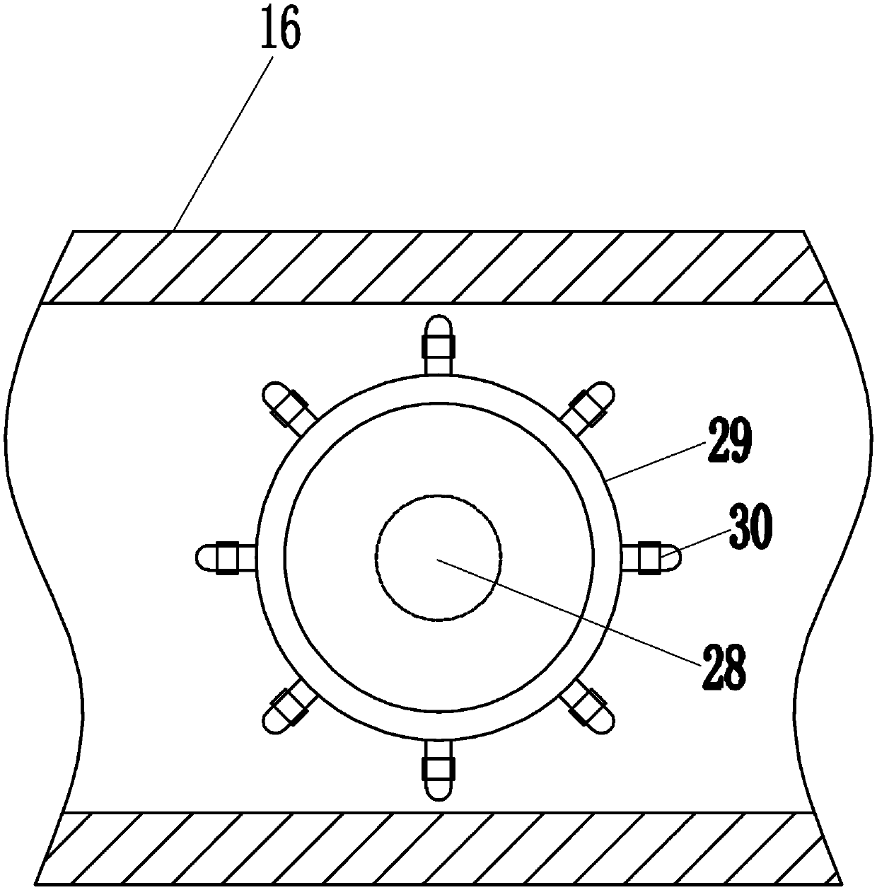
[0016] A material control type discharge valve, such as Figure 1-2 As shown, it includes a mounting plate 1, a first bolt 3, a first valve body 4, a first mounting block 5, a second mounting block 6, a valve seat 8, an adjustment mechanism 9, a connecting rod 10, a second valve body 11, Outlet pipe 13, water injection pipe 14, water supply pipe 15, return pipe 16, first compression spring 17 and piston 171, have two first threaded holes 2 on the mounting plate 1, are screwed with in the two first threaded holes 2 The first bolt 3, the first valve body 4 is threadedly connected on the two first bolts 3, the water injection pipe 14 is connected in the middle of the top of the first valve body 4, and the first valve body 4 is opened with a first valve for making water flow. Cavity 401, the first installation block 5 is fixedly connected to the middle part on the left side of the first valve body 4, the first valve body 4 is connected to the first installation block 5 by welding,...
Embodiment 2
[0018] A material control type discharge valve, such as Figure 1-2 As shown, it includes a mounting plate 1, a first bolt 3, a first valve body 4, a first mounting block 5, a second mounting block 6, a valve seat 8, an adjustment mechanism 9, a connecting rod 10, a second valve body 11, Outlet pipe 13, water injection pipe 14, water supply pipe 15, return pipe 16, first compression spring 17 and piston 171, have two first threaded holes 2 on the mounting plate 1, are screwed with in the two first threaded holes 2 The first bolt 3, the first valve body 4 is threadedly connected on the two first bolts 3, the water injection pipe 14 is connected in the middle of the top of the first valve body 4, and the first valve body 4 is opened with a first valve for making water flow. Cavity 401, the first installation block 5 is fixedly connected to the middle part on the left side of the first valve body 4, the second installation block 6 is fixedly connected to the middle part on the ri...
Embodiment 3
[0021] A material control type discharge valve, such as Figure 1-2 As shown, it includes a mounting plate 1, a first bolt 3, a first valve body 4, a first mounting block 5, a second mounting block 6, a valve seat 8, an adjustment mechanism 9, a connecting rod 10, a second valve body 11, Outlet pipe 13, water injection pipe 14, water supply pipe 15, return pipe 16, first compression spring 17 and piston 171, have two first threaded holes 2 on the mounting plate 1, are screwed with in the two first threaded holes 2 The first bolt 3, the first valve body 4 is threadedly connected on the two first bolts 3, the water injection pipe 14 is connected in the middle of the top of the first valve body 4, and the first valve body 4 is opened with a first valve for making water flow. Cavity 401, the first installation block 5 is fixedly connected to the middle part on the left side of the first valve body 4, the second installation block 6 is fixedly connected to the middle part on the ri...
PUM
 Abstract
Description
Claims
Application Information
 - R&D
- Intellectual Property
- Life Sciences
- Materials
- Tech Scout
- Unparalleled Data Quality
- Higher Quality Content
- 60% Fewer Hallucinations
Browse by: Latest US Patents, China's latest patents, Technical Efficacy Thesaurus, Application Domain, Technology Topic, Popular Technical Reports.
© 2025 PatSnap. All rights reserved.Legal|Privacy policy|Modern Slavery Act Transparency Statement|Sitemap|About US| Contact US: help@patsnap.com