
Heavy-loading large vacuum heat treatment furnace

A vacuum heat treatment furnace and large-scale technology, applied in heat treatment furnaces, heat treatment equipment, furnaces, etc., can solve the problems of insufficient cooling speed, insufficient hardenability, and excessive furnace loading, so as to accelerate the cooling speed and improve the permeability. Effect

Inactive Publication Date: 2019-08-02
苏州金言来真空炉业有限公司
View PDF2 Cites 1 Cited by
  • Summary
  • Abstract
  • Description
  • Claims
  • Application Information

AI Technical Summary

Problems solved by technology

[0002] With the continuous development of the metal processing industry, metal heat treatment has become an indispensable part; metal heat treatment has also developed from the original ordinary box-type heat treatment to vacuum heat treatment, and the current vacuum heat treatment has also developed from the original miniaturization to large-scale development; vacuum Heat treatment is roughly divided into oil quenching and gas quenching. Vacuum air quenching mainly relies on gas to achieve cooling, so the cooling rate is not enough and the hardenability is not enough if the furnace is too large.
Although the cooling speed of the vacuum oil quenching furnace is sufficient, because it is divided into two chambers, the loading and unloading of the material depends on the forklift in the cold room. If the workpiece is very long, the forklift cannot realize the unloading at all; The maximum loading capacity of the vacuum oil quenching furnace is only about 2 tons

Method used


Image

  • Heavy-loading large vacuum heat treatment furnace

Examples


Embodiment

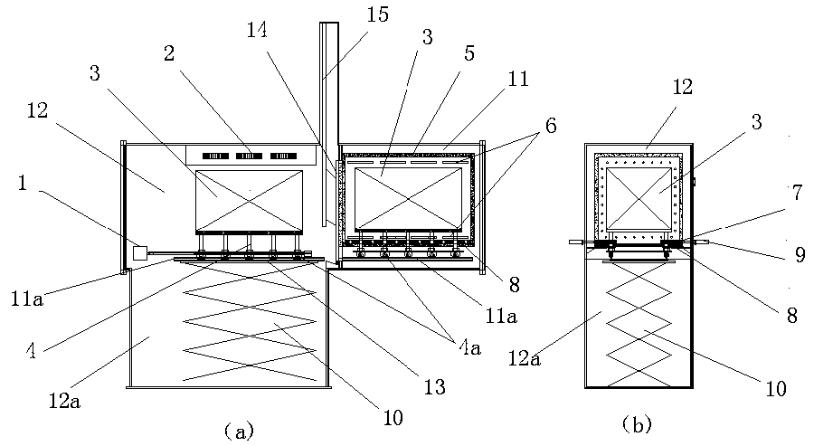
[0018] like figure 1 Shown is a structural diagram of a heavy-loading large-scale vacuum heat treatment furnace of the embodiment, wherein Figure a is a front view, and Figure b is a left view; a structural diagram of a heavy-loading large-scale vacuum heat-treatment furnace is mainly composed of a heating chamber 11 Consists of a cooling chamber 12, the heating chamber is a square structure, the heating chamber is provided with a fixed thermal insulation layer 5, and a plurality of heating sheets 6 are arranged up and down inside the fixed thermal insulation layer, and the bottom thermal insulation layer of the fixed thermal insulation layer 8 is provided with a movable insulation layer 7; the upper part of the cooling chamber is provided with a hot air circulation device 2, the middle is equipped with a rotating pallet 13, the lower part is provided with a quenching pool 12a, and the bottom of the annealing pool is equipped with a lifting mechanism 10, and the lifting mechani...


PUM


Abstract

The invention relates to a heavy-loading large vacuum heat treatment furnace. The heavy-loading large vacuum heat treatment furnace is mainly composed of a heating chamber and a cooling chamber; the heating chamber is of a square structure, a fixed heat preservation layer is arranged in the heating chamber, a plurality of heating pieces are arranged in the fixed heat preservation layer in an up-down mode, and a movable heat preservation layer is arranged above the heat preservation layer at the bottom of the fixed heat preservation layer; a hot air circulating device is arranged on the upper part of the cooling chamber, a rotary supporting plate is arranged in the middle of the cooling chamber, a quenching tank is arranged at the lower part of the cooling chamber, a lifting mechanism is arranged at the bottom of the quenching tank, and a rotary supporting plate is connected above the lifting mechanism; and rail grooves are formed in the middle of the movable heat preservation layer andthe rotary supporting plate, feeding trolleys can be borne on the rail grooves, the bottoms of the feeding trolleys are provided with movable rollers, the movable rollers linearly move on the rail grooves, and the heating chamber and the cooling chamber are connected through a movable door. According to the heavy-loading large-scale vacuum heat treatment furnace, a large-scale workpiece loading trolley can move between the heating chamber and the cooling chamber, the cooling speed is increased, and the hardenability of the quenching is improved.

Description

technical field [0001] The invention relates to the field of metal vacuum heat treatment, in particular to a heavy-load large-scale vacuum heat treatment furnace. Background technique [0002] With the continuous development of the metal processing industry, metal heat treatment has become an indispensable part; metal heat treatment has also developed from the original ordinary box-type heat treatment to vacuum heat treatment, and the current vacuum heat treatment has also developed from the original miniaturization to large-scale development; vacuum Heat treatment is roughly divided into two types: oil quenching and gas quenching. Vacuum air quenching mainly relies on gas to achieve cooling, so the cooling rate is not enough and the hardenability is not enough if the furnace is too large. Although the cooling speed of the vacuum oil quenching furnace is sufficient, because it is divided into two chambers, the loading and unloading of the material depends on the forklift in ...

Claims


Application Information

Patent Timeline
Patent Type & Authority Applications(China)
IPC IPC(8): C21D9/00C21D1/773C21D1/63
CPCC21D1/63C21D1/773C21D9/0006C21D9/0018
Inventor 李荣华
Owner 苏州金言来真空炉业有限公司
Learn More