Die-cutting manufacturing device for double-faced adhesive tape

A technology of double-sided tape and double-sided tape, which is applied in the direction of winding strips, sending objects, processing thin materials, etc., which can solve the problems of double-sided tape accumulation and low work efficiency.

Active Publication Date: 2019-08-02
重庆安洁电子有限公司
View PDF9 Cites 0 Cited by
  • Summary
  • Abstract
  • Description
  • Claims
  • Application Information

AI Technical Summary

Problems solved by technology

[0004] The purpose of the present invention is to provide a double-sided adhesive die-cutting production equipment to solve the problems of double-sided adhesive accumulation and low work efficiency in existing double-sided adhesive die-cutting machines

Method used


Image

  • Die-cutting manufacturing device for double-faced adhesive tape
  • Die-cutting manufacturing device for double-faced adhesive tape
  • Die-cutting manufacturing device for double-faced adhesive tape

Examples


Embodiment 1

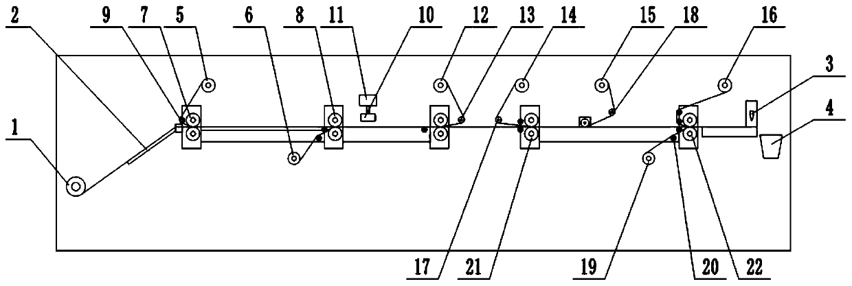
[0026] Embodiment one is basically as attached figure 1 , figure 2 Shown:

[0027] The double-sided tape die-cutting production equipment includes a frame, and the opposite ends of the frame are respectively set as a feed end and a discharge end, and five sets of conveyors for transmitting double-sided adhesive tape are connected in rotation between the feed end and the discharge end. Pair of rollers; the feeding end is provided with a discharge unit for releasing the double-sided adhesive tape, the discharge unit includes a discharge roller 1 that is rotatably connected to the frame, and the frame between the discharge unit and the first set of opposite rollers 7 The material guide plate 2 inclined to the discharge roller 1 is connected by bolts on the top, and a number of parallel guide rollers are connected to the material guide plate 2 in rotation; a die-cutting unit is provided on the discharge end, and the die-cutting unit includes vertical sliding The die cutter 3 th...

Embodiment 2

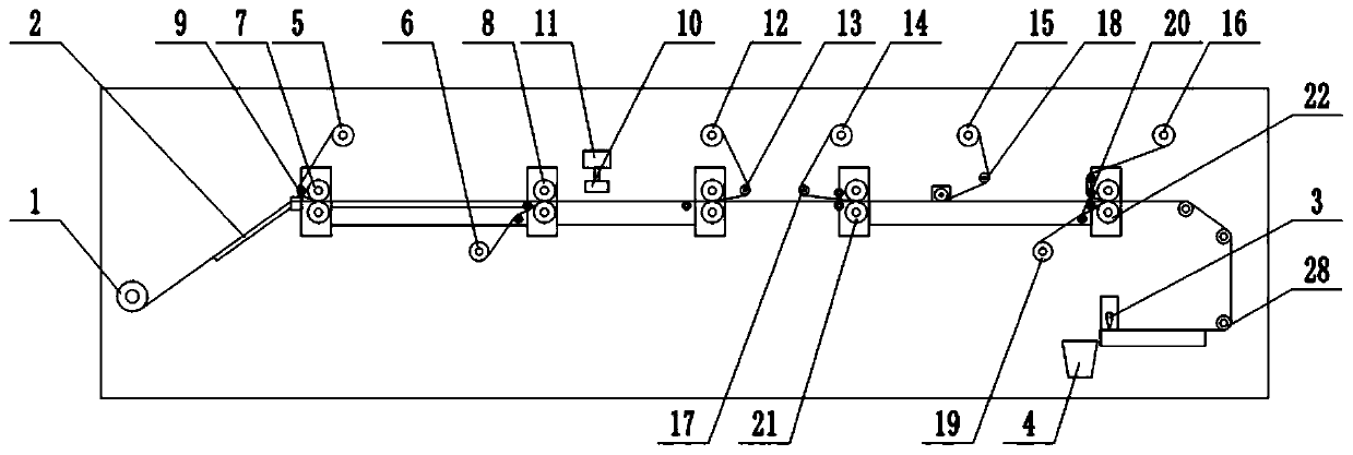
[0036] Embodiment two is basically as attached image 3 Shown:

[0037] This embodiment adds a turning mechanism on the basis of Embodiment 1, specifically: a turning mechanism for changing the front and back sides of the double-sided tape is provided between the double-sided tape reverse side processing mechanism and the die-cutting unit, and the turning mechanism Comprise at least two guide rollers 28 that are rotatably connected on the frame. In the present embodiment, the quantity of guide rollers 28 is three. The double-sided tape is conveyed to the die-cutting unit.

[0038] The pretreated double-sided tape is turned over by the turning mechanism, so that the side with the cut marks faces up, so that it is better to observe whether the cutting is accurate during cutting. Specifically, the transmission of the double-sided adhesive tape is turned by the guide roller 28, so that the double-sided adhesive tape turns over and then enters the die-cutting unit.


PUM


Abstract

The invention relates to the technical field of die-cutting devices, and discloses a die-cutting manufacturing device for double-faced adhesive tape. The die-cutting manufacturing device comprises a rack. Two opposite ends of the rack are separately a feeding end and a discharging end. A releasing unit used for releasing the double-faced adhesive tape is arranged at the feeding end. A die-cuttingunit is arranged at the discharging end. A tape pasting unit, a pre-die-cutting unit and a pre-processing unit are sequentially arranged on the rack. The tape pasting unit comprises a first tape releasing roller and a second tape releasing roller. The pre-die-cutting unit comprises a die-cutting tool. The pre-processing unit comprises a leftover material recovery mechanism, a double-faced adhesivetape front face processing mechanism and a double-faced adhesive tape back face processing mechanism. The leftover material recovery mechanism is used for recovering leftover materials generated after die-cutting. The double-faced adhesive tape front face processing mechanism is used for removing tape on the front side of the double-faced adhesive tape. The double-faced adhesive tape back face processing mechanism is used for removing tape on the back face of the double-faced adhesive tape. By adoption of the die-cutting manufacturing device for the double-faced adhesive tape, the problem that an existing double-faced adhesive tape die-cutting machine can cause accumulation of double-faced adhesive tape and is low in working efficiency is solved.

Description

technical field [0001] The invention relates to the technical field of die-cutting equipment, in particular to a double-sided adhesive die-cutting production equipment. Background technique [0002] In the production process of double-sided adhesive tape, in order to meet the market demand, it needs to be cut into products of different sizes. The traditional double-sided tape with handle needs to be punched twice to meet the requirements. The first punching is for the non-adhesive area of ​​the handle, and the second is for positioning the periphery of the molding. This method is likely to lead to qualified products after cutting due to human factors. The rate is low, and there are certain security risks. [0003] Therefore, there is a double-sided tape die-cutting machine in the prior art, which can automatically die-cut the double-sided adhesive tape. After the double-sided adhesive tape has been die-cut, it is transported by the conveyor belt. On the shelf, personnel ne...

Claims


Application Information

Patent Timeline
Patent Type & Authority Applications(China)
IPC IPC(8): B65H37/04B65H23/188B65H23/26B65H35/02B65H19/30
CPCB65H19/30B65H23/1888B65H23/26B65H35/02B65H37/04B65H2701/3772
Inventor 淡克平
Owner 重庆安洁电子有限公司
Why Eureka
Try Eureka