


Quick Research
Generate reliable direction feasibility study reports for your R&D in just a few steps.

Technical Q&A
Discover and master advanced knowledge NOW. Basics, ideas, possibilities, all at once.

Find Solutions
As an expert in R&D theories, this can generate solutions to your technical problems instantly.

Evaluate Feasibility
Analyze your overall solution with one click, know your potential R&D risks in advance.

Monitor Landscape
Get weekly tech updates, stay abreast of the latest tech innovations and key insights.
How to make die-cut indentation bottom plate
A production method and indentation technology, which are applied in the directions of processing and manufacturing, manufacturing auxiliary devices, processing data acquisition/processing, etc., can solve the problems of die-cutting position affecting accuracy and low efficiency, so as to improve significance, automation, and The effect of precision
- Summary
- Abstract
- Description
- Claims
- Application Information
AI Technical Summary
Problems solved by technology
Method used
Image

Examples
Embodiment Construction
[0034] It should be understood that the specific embodiments described here are only used to explain the present invention, not to limit the present invention.
[0035] refer to figure 1 , figure 1 It is a schematic flow chart of the first embodiment of the present invention.
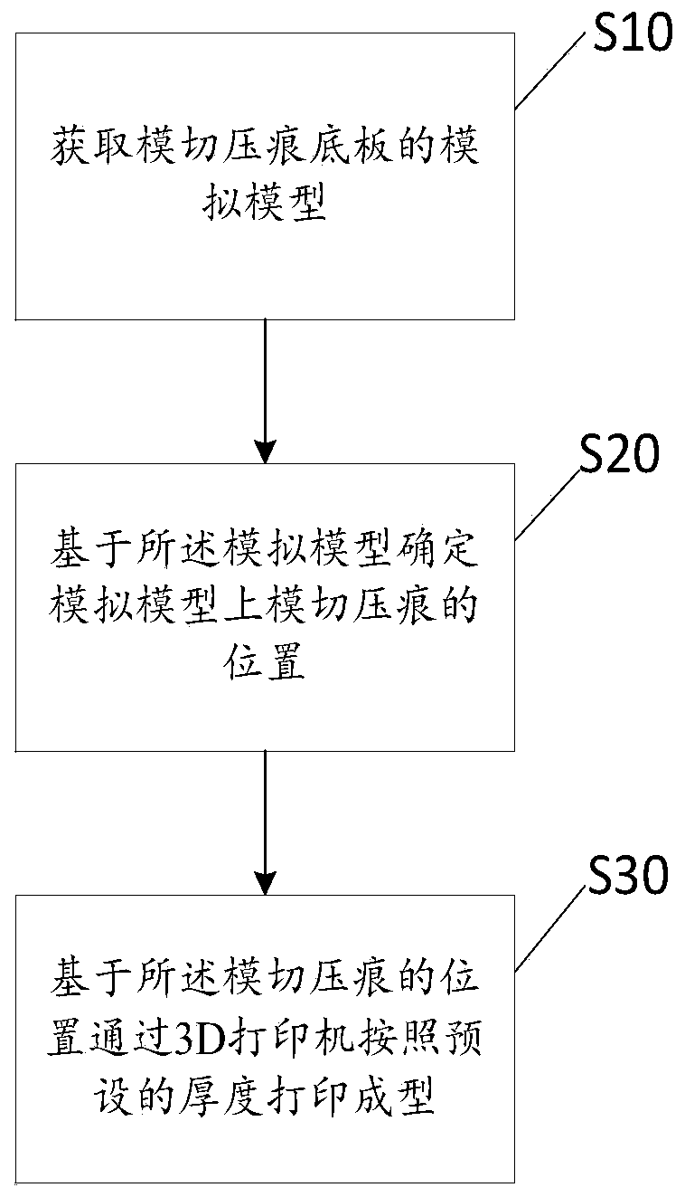
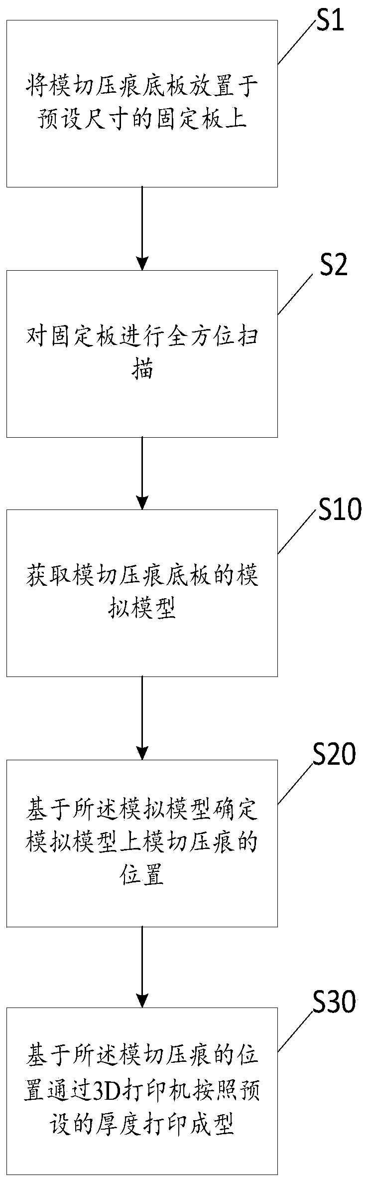
[0036] Such as figure 1 Shown, the manufacture method of die-cutting indentation bottom plate of the present invention, comprises the following steps:
[0037] Step S10, obtaining the simulation model of the die-cutting indentation base plate;
[0038] In step S10, the 3D printer is based on the readable production file about the die-cutting and indentation base plate sent by the mobile phone or the computer, and the three-dimensional simulation model is displayed after the production file is opened. That is, the simulation model is a three-dimensional design file. In this paper, the 3D printer is connected to a computer or a mobile phone, and the user sends the graphic design on the computer or th...
PUM
 Abstract
Description
Claims
Application Information
 - R&D Engineer
- R&D Manager
- IP Professional
- Industry Leading Data Capabilities
- Powerful AI technology
- Patent DNA Extraction
Browse by: Latest US Patents, China's latest patents, Technical Efficacy Thesaurus, Application Domain, Technology Topic, Popular Technical Reports.
© 2024 PatSnap. All rights reserved.Legal|Privacy policy|Modern Slavery Act Transparency Statement|Sitemap|About US| Contact US: help@patsnap.com