
Plastic granulating device and method thereof

A pelletizing and plastic technology, applied in coating and other directions, can solve the problems of unsatisfactory performance of PVC cable material, lack of cooling and drying functions, single function of cutting machine, etc., so as to improve the quality of subsequent processing and ensure cutting. Material efficiency, novel structure design effect

Inactive Publication Date: 2019-08-02
龚有晨
View PDF9 Cites 2 Cited by
  • Summary
  • Abstract
  • Description
  • Claims
  • Application Information

AI Technical Summary

Problems solved by technology

[0002] With people's emphasis on environmental protection and safety, the performance of traditional PVC cable materials cannot meet the current market demand, and the proportion of low-smoke and halogen-free cable materials in the market is gradually increasing.
In the production process, using plastic extruder to extrude, water-cooled, and air-dried to pelletize is the most common and general-purpose processing method. However, there is a phenomenon of bending of the plastic strip before entering the pelletizer, which leads to cutting The uniformity is poor. In addition, the existing cutting machine has a single function, which only has the function of cutting materials, and does not have the functions of cooling and drying, resulting in low production efficiency. Therefore, it is necessary to improve

Method used


Image

  • Plastic granulating device and method thereof
  • Plastic granulating device and method thereof
  • Plastic granulating device and method thereof

Examples


Embodiment Construction

[0028] The technical solutions in the embodiments of the present invention will be clearly and completely described below in conjunction with the accompanying drawings in the embodiments of the present invention. Obviously, the described embodiments are only a part of the embodiments of the present invention, rather than all the embodiments. Based on the embodiments of the present invention, all other embodiments obtained by those of ordinary skill in the art without creative work shall fall within the protection scope of the present invention.

[0029] In the description of the present invention, it should be noted that the terms "upper", "lower", "inner", "outer", "front end", "rear end", "both ends", "one end", "the other end" The orientation or positional relationship of other indications is based on the orientation or positional relationship shown in the drawings, which is only used to facilitate the description of the present invention and simplify the description, and does ...


PUM


Abstract

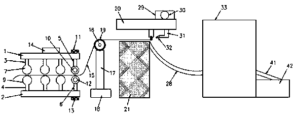
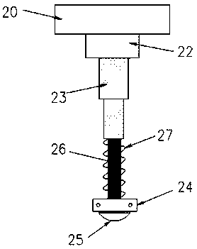
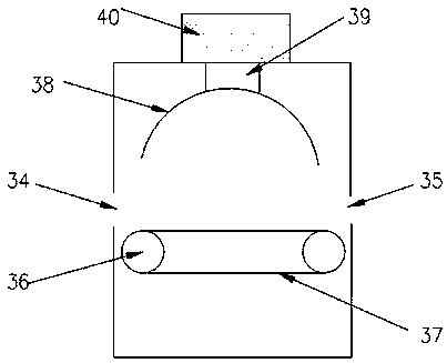
The invention discloses a plastic granulating device and a method thereof. The plastic granulating device comprises a conveying mechanism, a guide component and a material cutting mechanism, a coolingmechanism and a drying mechanism, wherein the conveying mechanism comprises an upper bracket, a lower bracket, first roller brackets and second roller brackets, a first conveying wheel installation frame and a second conveying wheel installation frame. The lower end of the upper bracket is provided with a plurality of the first roller wheel brackets, wherein each first roller wheel bracket is provided with a corresponding first roller wheel. The upper end of the lower support is provided with the second roller wheel brackets which are symmetrical in respect to the first roller wheel brackets,wherein each second roller wheel bracket is provided with a corresponding second roller wheel. The first conveying wheel installation frame is arranged at the right end part of the lower end surfaceof the upper bracket, and the second conveying wheel installation frame is arranged on the right end part of the upper end surface of the lower bracket. The guide component is arranged on one side ofthe conveying mechanism, the material cutting mechanism is arranged on the right side of the guide component, and the cooling mechanism is arranged on the right side of the material cutting mechanism.The plastic granulating device and the method thereof has the advantages of being novel in structural design and high in automation degree, and can achieve the conveying, grain cutting, cooling and drying of plastic strips and obtain high efficiency and good uniformity in the grain cutting.

Description

Technical field [0001] The invention relates to the technical field of pelletizing, in particular to a plastic pelletizing device and method. Background technique [0002] As people pay more attention to environmental protection and safety, the performance of traditional PVC cable materials cannot meet the current market demand, and the proportion of low-smoke halogen-free cable materials in the market is gradually increasing. In the production process, the use of plastic extruder for extrusion molding, water cooling, air-drying and pelletizing are the most common processing methods. However, the plastic strips before entering the cutter for pelletizing are bent, resulting in cutting The uniformity is poor. In addition, the existing cutting machine has a single function, only has the cutting function, and does not have the cooling and drying functions, resulting in low production efficiency. Therefore, it is necessary to improve. Summary of the invention [0003] The purpose of t...

Claims


Application Information

Patent Timeline
Patent Type & Authority Applications(China)
IPC IPC(8): B29B9/06B29B9/16
CPCB29B9/06B29B9/16
Inventor 龚有晨
Owner 龚有晨
Learn More