
A plate mesh cage transfer device

A transfer device, mesh cage technology, applied in auxiliary devices, auxiliary welding equipment, welding equipment and other directions, can solve the problems of waste of human resources, product quality decline, low efficiency, etc., to improve the level of automation, improve production efficiency, efficient automatic The effect of transshipment

Active Publication Date: 2021-05-25
ANHUI KEDA IND CO LTD
View PDF0 Cites 0 Cited by
  • Summary
  • Abstract
  • Description
  • Claims
  • Application Information

AI Technical Summary

Problems solved by technology

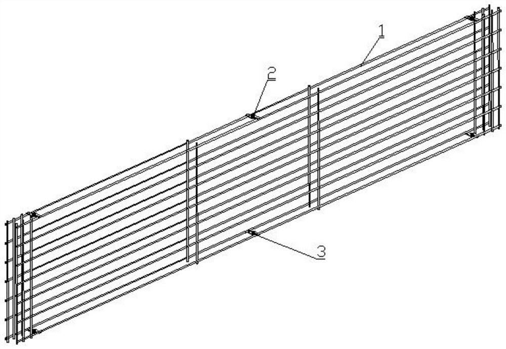
[0002] In the production of autoclaved aerated concrete block slabs, a large number of steel mesh cages are required. At present, most manufacturers still rely on manual welding of steel mesh cages. The size of the steel mesh cages produced by this method is Different sizes make it difficult to meet the specified process requirements, which not only directly affects subsequent production, but also causes a decline in product quality; after the steel mesh cage is welded, it is necessary to transfer the welded steel mesh cage to the next station. Due to its structural reasons, it is difficult to cooperate with the transfer device for transfer. Most production companies also rely on manual handling, and then organize them to meet the operational requirements of the next process. Some manufacturers rely on simple The clamp is used for grabbing and transferring, but it still needs to be sorted manually before proceeding to the next process. This transfer method is labor-intensive, time-consuming, inefficient, wastes human resources, and is not conducive to the improvement of production automation.

Method used


Image

  • A plate mesh cage transfer device
  • A plate mesh cage transfer device
  • A plate mesh cage transfer device

Examples


Embodiment Construction

[0027] The present invention will be further described in detail below in conjunction with the accompanying drawings, so that those skilled in the art can understand more clearly.

[0028] Such as Figure 8 , Figure 9 , Figure 10 , Figure 11 As shown, the present invention includes:

[0029] Including a frame 21, a movable connection walking assembly on the frame, a movable connection lifting assembly on the walking assembly, and a cage positioning assembly;

[0030] Described walking assembly comprises, walking frame 22, is connected on a frame of walking frame 23 walking speed reduction boxes, and the input end of walking speed reduction box is connected walking motor 24, and the two ends of walking speed reduction box are respectively connected left walking transmission shaft 25, right walking transmission shaft. Shaft 26, the left and right travel transmission shafts rotate respectively to connect the travel frame, the ends of the left and right travel transmission ...


PUM


Abstract

The invention discloses a plate mesh cage transfer device, which includes a frame, a movable connecting walking assembly on the frame, a movable connecting lifting assembly on the walking assembly, and a mesh cage welding positioning assembly; the walking assembly It includes a walking frame, a frame of the walking frame is connected with a traveling reduction box, and the input end of the walking reduction box is connected with a traveling motor; Motor; the cage welding positioning assembly includes a base, and guide rails are provided on both sides of the top surface of the base, and the front end and rear end of the guide rail are respectively movable to connect the end mechanism, the end mechanism at the front end and the end mechanism at the rear end The mirror image is symmetrical; the front end and the rear end of the guide rail are movably connected to several middle mechanisms. The invention can realize high-efficiency automatic transfer of the plate mesh cage, greatly improves the automation level of plate mesh cage transfer, saves human resources, and improves production efficiency.

Description

technical field [0001] The invention belongs to the technical field of building material production, and in particular relates to a board cage transfer device. Background technique [0002] In the production of autoclaved aerated concrete block slabs, a large number of steel mesh cages are required. At present, most manufacturers still rely on manual welding of steel mesh cages. The size of the steel mesh cages produced by this method is Different sizes make it difficult to meet the specified process requirements, which not only directly affects subsequent production, but also causes a decline in product quality; after the steel mesh cage is welded, it is necessary to transfer the welded steel mesh cage to the next station. Due to its structural reasons, it is difficult to cooperate with the transfer device for transfer. Most production companies also rely on manual handling, and then organize them to meet the operational requirements of the next process. Some manufacturers ...

Claims


Application Information

Patent Timeline
Patent Type & Authority Patents(China)
IPC IPC(8): B23K37/04B23K37/00E04C5/01B23K101/22
CPCB23K37/00B23K37/0443E04C5/01
Inventor 吴亚军张长江王航滕元祥徐顺武
Owner ANHUI KEDA IND CO LTD
Learn More