
Plate mesh cage and plate mesh cage welding and positioning and transferring devices

A transfer device, welding positioning technology, applied in the direction of auxiliary equipment, welding equipment, auxiliary welding equipment, etc., can solve the problems of affecting production, labor-intensive, different sizes, etc.

Active Publication Date: 2019-08-02
ANHUI KEDA IND CO LTD
View PDF6 Cites 8 Cited by
  • Summary
  • Abstract
  • Description
  • Claims
  • Application Information

AI Technical Summary

Problems solved by technology

[0002] In the production of autoclaved aerated concrete block slabs, a large number of steel mesh cages are required. At present, most manufacturers still rely on manual welding of steel mesh cages. The size of the steel mesh cages produced by this method is Different sizes make it difficult to meet the specified process requirements, which not only directly affects subsequent production, but also causes a decline in product quality; after the steel mesh cage is welded, it is necessary to transfer the welded steel mesh cage to the next station. Due to its structural reasons, it is difficult to cooperate with the transfer device for transfer. Most production companies also rely on manual handling, and then organize them to meet the operational requirements of the next process. Some manufacturers rely on simple The clamp is used for grabbing and transferring, but it still needs to be sorted manually before proceeding to the next process. This transfer method is labor-intensive, time-consuming, inefficient, wastes human resources, and is not conducive to the improvement of production automation.

Method used


Image

  • Plate mesh cage and plate mesh cage welding and positioning and transferring devices
  • Plate mesh cage and plate mesh cage welding and positioning and transferring devices
  • Plate mesh cage and plate mesh cage welding and positioning and transferring devices

Examples


Embodiment Construction

[0035] The present invention will be further described in detail below in conjunction with the accompanying drawings, so that those skilled in the art can understand more clearly.

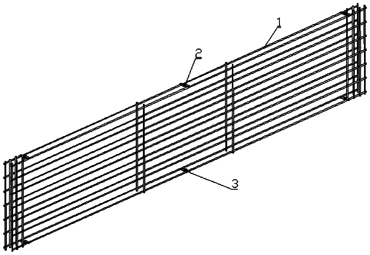
[0036] As plate net cage of the present invention, as figure 1 , figure 2 , image 3 shown, including:

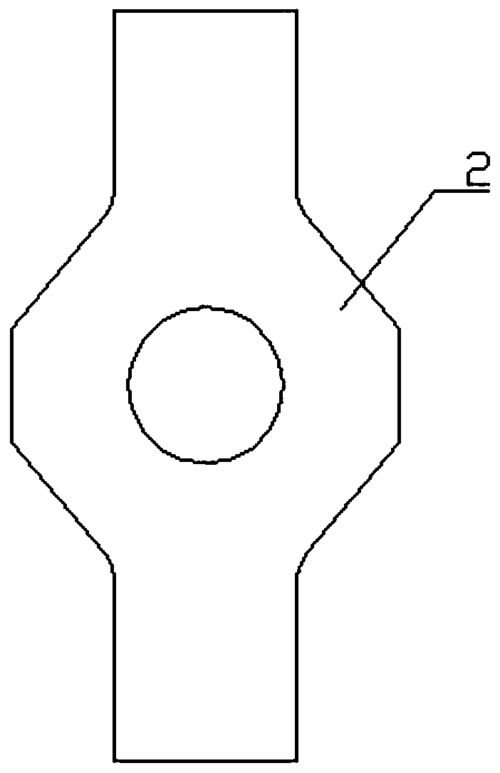
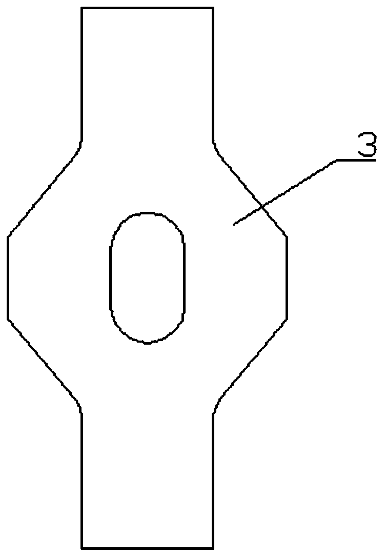
[0037] The cage body 1, the upper part of the cage body is connected to several upper connecting pieces 2 along the length direction, and the upper connecting piece is provided with a circular through hole, and the lower part of the cage body is connected to several lower connecting pieces 3 along the length direction, The lower connecting piece is provided with waist-shaped through holes, and the waist-shaped through holes communicate with the circular through holes one by one.

[0038] The length of the waist-shaped through hole is not less than the diameter of the circular through hole, and the width of the waist-shaped through hole is smaller than the diameter of the circular through hol...


PUM


Abstract

The invention discloses a plate mesh cage and plate mesh cage welding and positioning and transferring devices. The plate mesh cage comprises a mesh cage body. The upper portion of the mesh cage bodyis connected with multiple upper connecting pieces in the length direction, and the lower portion of the mesh cage body is connected with multiple lower connecting pieces in the length direction. A plate mesh cage welding and positioning device comprises a base, guide rails, end assemblies connected with the guide rails, and multiple middle assemblies. A plate mesh cage transferring device comprises a rack. A walking assembly is movably connected to the rack, a lifting assembly is connected to the walking assembly, and the lower portion of the lifting assembly is connected with a locking mechanism. The plate mesh cage has a specific connecting structure, and can tightly cooperate with the plate mesh cage transferring device under the assistance of the plate mesh cage welding and positioning device to achieve efficient automatic transferring. Meanwhile, the plate mesh cage welding and positioning device further achieves the effects of normalizing the sizes and the flatness of mesh cagesin the welding process and improving the welding process and the automation degree.

Description

technical field [0001] The invention belongs to the technical field of building material production, and in particular relates to a plate mesh cage, a plate mesh cage welding positioning and shipping device. Background technique [0002] In the production of autoclaved aerated concrete block slabs, a large number of steel mesh cages are required. At present, most manufacturers still rely on manual welding of steel mesh cages. The size of the steel mesh cages produced by this method is Different sizes make it difficult to meet the specified process requirements, which not only directly affects subsequent production, but also causes a decline in product quality; after the steel mesh cage is welded, it is necessary to transfer the welded steel mesh cage to the next station. Due to its structural reasons, it is difficult to cooperate with the transfer device for transfer. Most production companies also rely on manual handling, and then organize them to meet the operational requi...

Claims


Application Information

Patent Timeline
IPC IPC(8): B23K37/04B23K37/00E04C5/01B23K101/22
CPCB23K37/00B23K37/0443E04C5/01
Inventor 吴亚军张长江王航滕元祥徐顺武
Owner ANHUI KEDA IND CO LTD
Learn More