3D printing microfluidic device and large-flux monodisperse emulsion preparation method based on same
A 3D printing and microfluidic technology, applied in the field of microfluidics, can solve the problems of microfluidic chip preparation of droplets in small quantities, rough structure of microfluidic chips, and difficult industrial production, etc., and achieves excellent monodispersity, Simple structure and easy operation
- Summary
- Abstract
- Description
- Claims
- Application Information
AI Technical Summary
Problems solved by technology
Method used
Image


Examples
Embodiment 1
[0038] The channels and slits are printed as a whole to form a sheet-like rectangular structure with two rows and 6 channels. The dispersed phase distribution device is a thicker shell structure, and then the two are combined with AB glue. The dispersed phase is injected using a syringe pump. The resulting microfluidic device is shown in Figure (1). The dispersed phase used is water, the total pipe flow rate is 30ml / h, and the continuous phase is dimethyl oil bath silicone oil. Since the viscosity of silicone oil is 50cs. The syringe pump uses the laboratory micro-syringe pump LSP01-1A of LongerPump Company. , Dowcorning 749 was added as a surfactant in the oil phase, its mass concentration was 5wt%, and a monodisperse emulsion with uniform and controllable size could be obtained.
Embodiment 2
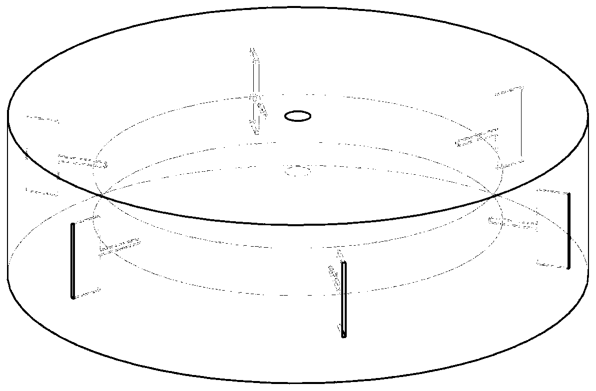
[0040]The shape of the device is circular pie, and there is a cylindrical liquid storage tank with a diameter of 24mm and a height of 3mm inside. The device has 12 channels evenly arranged, the central angle between each channel is 30°, and the slit is on the side of the device. The microfluidic device is shown in Figure (2), and the specific structural parameters are shown in Figure (4). The dispersed phase used is water, the total pipe flow rate is 30ml / h, and the continuous phase is dimethyl oil bath silicone oil. Since the viscosity of silicone oil is 50cs. The syringe pump uses the laboratory micro-syringe pump LSP01-1A of LongerPump Company. , added Dowcorning 749 as a surfactant in the oil phase, and its mass concentration was 5wt%. Under the above conditions, experiment with this microfluidic device, the device produces continuous droplets with uniform size, and more than 90% of the droplets have a diameter distribution of 0.8-1.2m and uniform size, as shown in Figu...
Embodiment 3
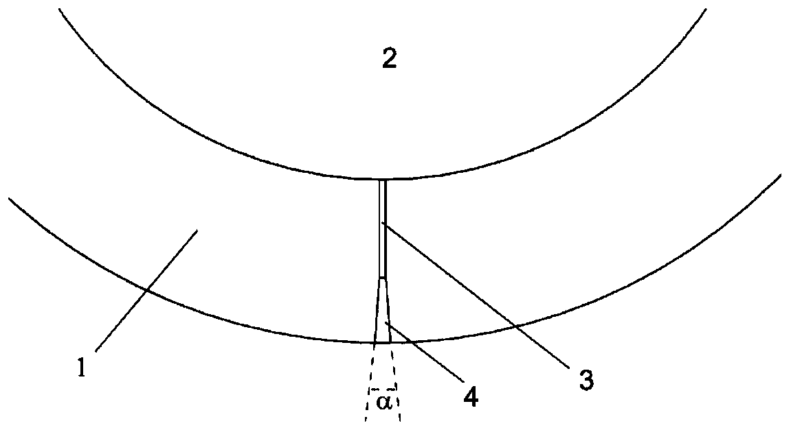
[0042] The shape of the device is circular pie, and there is a cylindrical liquid storage tank with a diameter of 24mm and a height of 3mm inside. This device has 6 channels evenly arranged, and the central angle between each channel is 60°. The slit is on the side of the device, and the corresponding inclination angle is set in the slit area, that is, the top and bottom walls of the slit An inclination angle of α is opened from the connecting channel to the outside to control the size of the generated droplets. The microfluidic device is shown in Figure (3). The dispersed phase used is water, the total pipe flow rate is 30ml / h, and the continuous phase is dimethyl oil bath silicone oil. Since the viscosity of silicone oil is 50cs. The syringe pump uses the laboratory micro-syringe pump LSP01-1A of LongerPump Company. , added Dowcorning 749 as a surfactant in the oil phase, and its mass concentration was 5wt%. Under the above conditions, the microfluidic device is used for...
PUM
| Property | Measurement | Unit |
|---|---|---|
| Width | aaaaa | aaaaa |
| Height | aaaaa | aaaaa |
Abstract
Description
Claims
Application Information
 - Generate Ideas
- Intellectual Property
- Life Sciences
- Materials
- Tech Scout
- Unparalleled Data Quality
- Higher Quality Content
- 60% Fewer Hallucinations
Browse by: Latest US Patents, China's latest patents, Technical Efficacy Thesaurus, Application Domain, Technology Topic, Popular Technical Reports.
© 2025 PatSnap. All rights reserved.Legal|Privacy policy|Modern Slavery Act Transparency Statement|Sitemap|About US| Contact US: help@patsnap.com