Brightness enhancement film
A technology of brightness enhancement film and polymer layer, applied in the field of communication, can solve problems such as non-directional scattering and total reflection, and achieve the effect of accurate identification and verification
- Summary
- Abstract
- Description
- Claims
- Application Information
AI Technical Summary
Problems solved by technology
Method used
Image

Examples
Embodiment 1
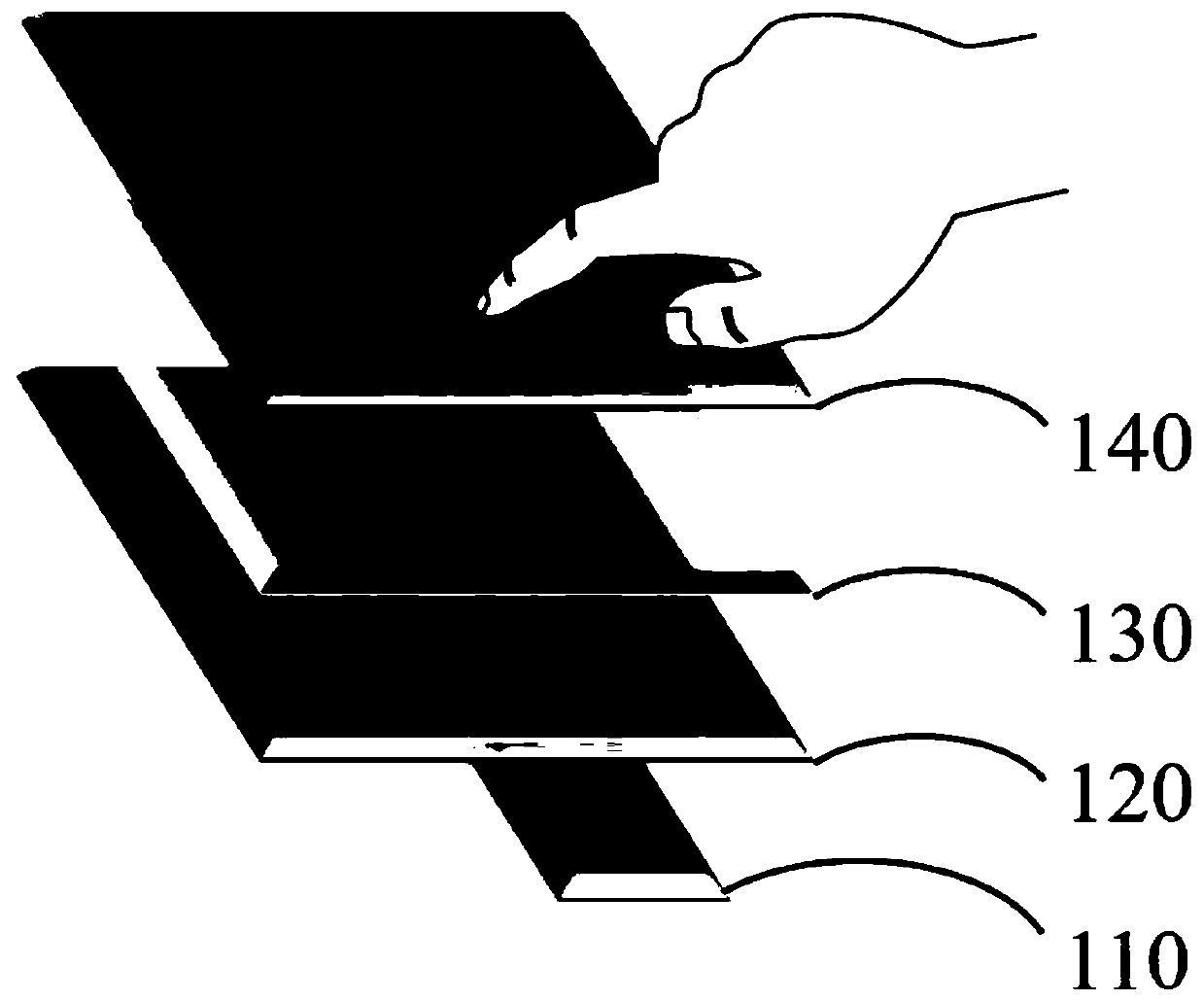
[0036] First, through Figure 4 , Figure 5 , Figure 7 , the brightness enhancing film of Example 1 of the present invention will be described. According to Embodiment 1 of the present invention applied to a backlight module, a conventional backlight module includes a light source 221 and a light guide plate 220 disposed on one side of the light source 221, a reflective sheet 210 disposed below the light guide plate 220, and disposed on the upper side of the light guide plate 220 The diffusion sheet 230 is the brightness enhancement film 240 arranged on the upper side of the diffusion sheet; wherein, the surface of the substrate 2401 of the brightness enhancement film 240 is provided with a plurality of lens structures 2402 and a plurality of platform structures 2403; the platform structure includes a platform part 24031; the platform structure It is arranged between the plurality of lens structures 2402 so that external light is substantially vertically incident and substa...
Embodiment 2
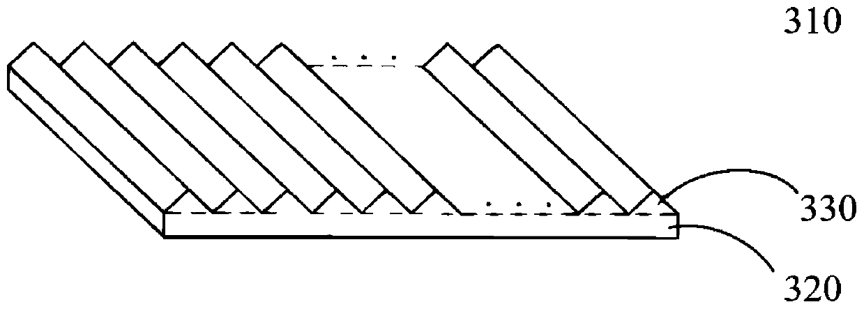
[0043] Please refer to Figure 9 , is a cross-sectional structure diagram of the first polymer layer 310 and the second polymer layer 320 of the brightness enhancement film of the second embodiment of the present invention. In the following, only the differences between Embodiment 2 and Embodiment 1 will be described, and the similarities will not be repeated here. The second polymer layer 320 of the brightness enhancement film is only provided with a lens structure 2402, and no platform structure is provided. 2403. At this time, the light can be condensed and diverged by the lens structure 2402 to uniformize the light respectively emitted by the first polymer layer 310 and avoid the situation of uneven light output (Mura).
Embodiment 3
[0045] Please refer to Figure 10 , is a cross-sectional structure diagram of the first polymer layer 310 and the second polymer layer 320 of the brightness enhancement film according to the third embodiment of the present invention. In the following, only the differences between Embodiment 3 and Embodiment 1 will be described, and the similarities will not be repeated here. The upper surface of the first polymer layer 310 of the brightness enhancement film is provided with a platform structure 2403A with a trapezoidal cross-section. A platform structure 2403B is disposed on the lower surface of the first polymer layer 310 opposite to the platform structure 2403A. Here, the platform structure 2403B is made of the same material as the first polymer layer 310 , and is disposed in the gap of the lens structure 2402 array.
[0046] The platform structure 2403C on the second polymer layer 320 is made of the same material as the second polymer layer 320 , and is disposed in the gap...
PUM
 Abstract
Description
Claims
Application Information
 - Generate Ideas
- Intellectual Property
- Life Sciences
- Materials
- Tech Scout
- Unparalleled Data Quality
- Higher Quality Content
- 60% Fewer Hallucinations
Browse by: Latest US Patents, China's latest patents, Technical Efficacy Thesaurus, Application Domain, Technology Topic, Popular Technical Reports.
© 2025 PatSnap. All rights reserved.Legal|Privacy policy|Modern Slavery Act Transparency Statement|Sitemap|About US| Contact US: help@patsnap.com