Door lock provided with anti-forgetting article placing table
A storage table and anti-forgetting technology, applied in the field of mechanical locks, can solve problems such as lost items, difficult to find items, forgotten items, etc., to reduce man-made damage, prevent accidental fall, and cheap installation
- Summary
- Abstract
- Description
- Claims
- Application Information
AI Technical Summary
Problems solved by technology
Method used
Image
Examples
Embodiment 1
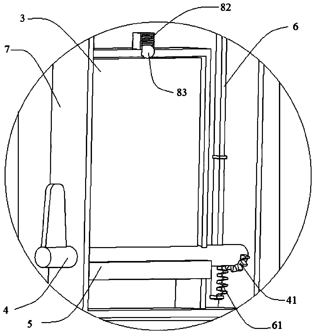
[0040] Such as figure 1 , 2 As shown, the present embodiment provides a door lock provided with an anti-forgetting storage table, installed on the door panel 100 and the door frame, including a lock body mechanism and a storage table mechanism; including a lock body mechanism and a storage table mechanism; the lock body The mechanism includes a lock assembly 1 and a lock 2; the lock body mechanism includes a lock assembly 1 and a lock 2; the lock assembly 1 includes a lock 12; one end of the lock 12 near the lock 2 is provided with The lock tongue 11 that can be inserted into the lock buckle 2 or withdraw from the lock buckle 2, the lock tongue 11 and the lock head 12 are connected as one; the lock head 12 is provided with a pin hole 122; the storage table mechanism includes a storage board 3, The rotating shaft 4 that drives the storage plate 3 to rotate, the latch rod 6 that moves up and down as the rotating shaft 4 rotates, and the bottom plate 5 that is fixedly installed ...
Embodiment 2
[0048] This embodiment is improved on the basis of Embodiment 1, and its improvements are as follows: figure 1 , 2 As shown, the door lock also includes an installation box 7 for installing the lock head assembly 1 and the storage plate 3 on the door panel 100 or the door frame, and the two ends of the rotating shaft 4 are rotatably connected to the two side walls of the installation box 7; The lock head 12 passes through the side of the installation box 7 close to the lock buckle 2 and is slidably connected with the installation box 7; the storage board 3 and the latch rod 6 are arranged in the installation box 7; the installation box 7 is provided with a box cover 71 And the isolation plate 72, the box cover 71 covers the area on the installation box 7 that does not correspond to the storage plate 3; the storage plate 3 and the latch rod 6 are respectively located on both sides of the isolation plate 72.
[0049] That is: the box cover 71 is provided with a through hole cor...
Embodiment 3
[0054] This embodiment is improved on the basis of Embodiments 1 to 3, and the improvements are as follows: Figure 4 , 5 As shown, the installation box 7 is also provided with a resistance mechanism 8 that provides resistance for putting down the storage board 3 to prevent the storage board 3 from falling down accidentally. The side of the installation box 7 away from the buckle 2 is provided with a resistance groove 73 and a resistance mechanism 8 installed in the resistance groove 73; the resistance groove 73 is vertically intersected with the through hole on the installation box 7 for the shaft 4 to pass through The resistance mechanism 8 includes a block 81 and a resistance spring 82, the block 81 is installed at one end of the resistance spring 82; When the storage board 3 is in the retracted state, the block 81 will be pressed against the rotating shaft 4 by the thrust of the resistance spring 82, so that the rotating shaft 4 will be subjected to greater resistance dur...
PUM
 Abstract
Description
Claims
Application Information
 - R&D Engineer
- R&D Manager
- IP Professional
- Industry Leading Data Capabilities
- Powerful AI technology
- Patent DNA Extraction
Browse by: Latest US Patents, China's latest patents, Technical Efficacy Thesaurus, Application Domain, Technology Topic, Popular Technical Reports.
© 2024 PatSnap. All rights reserved.Legal|Privacy policy|Modern Slavery Act Transparency Statement|Sitemap|About US| Contact US: help@patsnap.com


