Eureka AIR delivers breakthrough ideas for toughest innovation challenges, trusted by R&D personnel around the world.

Splicing apparatus on textile machine

A textile machine and beam installation technology, which is applied in textiles, looms, textiles, and papermaking, can solve the problems of high yarn cost, defects, and increased production costs, and achieve textile quality assurance, wide application range, and structural simple effect

Inactive Publication Date: 2019-07-26
枝江市劳士德纺织有限公司
View PDF0 Cites 0 Cited by
  • Summary
  • Abstract
  • Description
  • Claims
  • Application Information

AI Technical Summary

Problems solved by technology

[0002] In the field of textile technology, during the weaving process of the textile machine, the yarn often breaks during the weaving process. If the weaving continues, there will be defects, which will affect the product quality.
At the same time, most of today's factories use larger-width looms. When narrower cloth is needed, two cloths can be woven in one and then divided in the middle; The lower yarn is woven into the edge fabric of the cloth, and these edge fabrics will be cut off in the later processing without affecting the product quality; if two fabrics are woven in one, the edge fabric at the middle split position is woven with high-priced yarn made, increasing the production cost

Method used

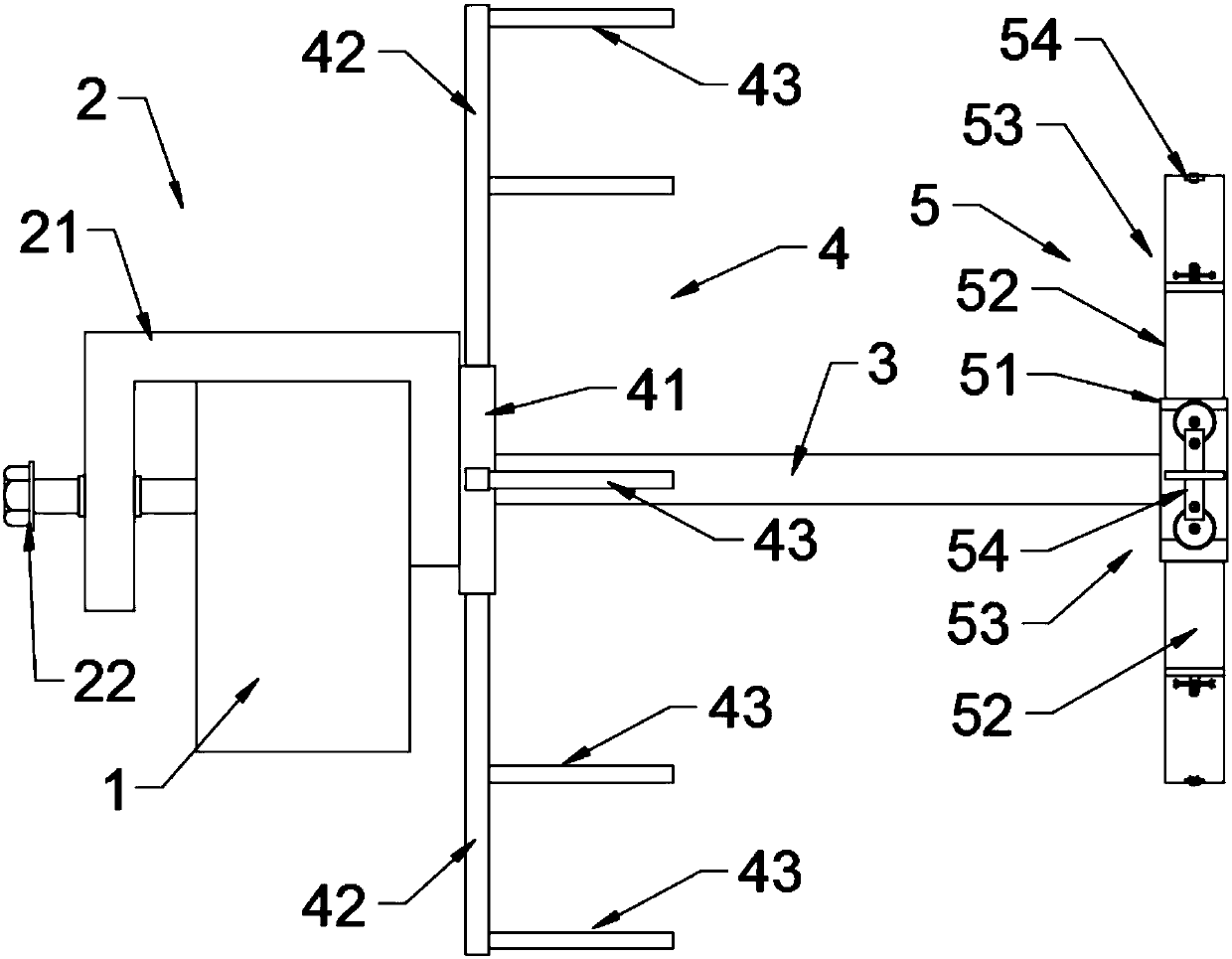
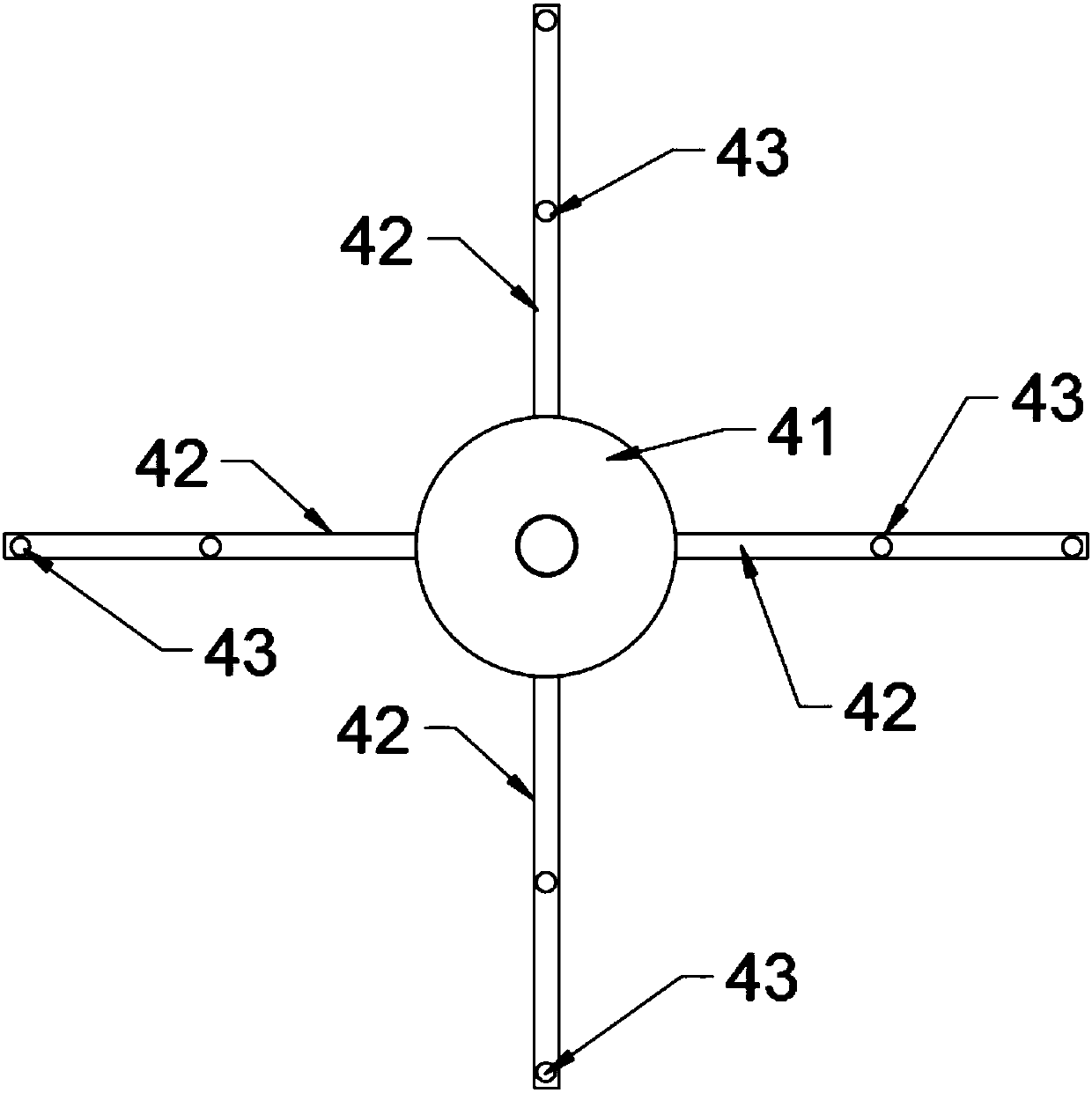
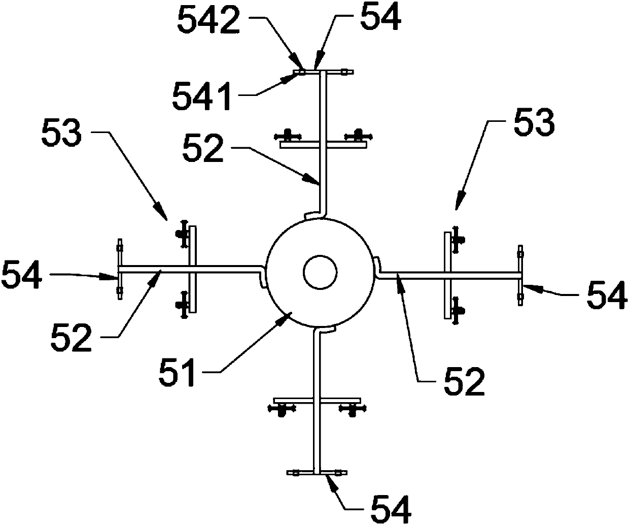

Image

  • Splicing apparatus on textile machine
  • Splicing apparatus on textile machine
  • Splicing apparatus on textile machine

Examples


Embodiment Construction

[0029] The technical solutions of the present invention will be clearly and completely described below in conjunction with the accompanying drawings. In the description of the present invention, it should be noted that the terms "center", "upper", "lower", "left", "right", "vertical", "horizontal", "inner", "outer" etc. The indicated orientation or positional relationship is based on the orientation or positional relationship shown in the drawings, and is only for the convenience of describing the present invention and simplifying the description, rather than indicating or implying that the referred device or element must have a specific orientation, or in a specific orientation. construction and operation, therefore, should not be construed as limiting the invention. In addition, the terms "first", "second", and "third" are used for descriptive purposes only, and should not be construed as indicating or implying relative importance.

[0030] In the description of the present...


PUM


Abstract

The invention belongs to the technical field of textiles and relates to a splicing apparatus on a textile machine. The splicing apparatus comprises a mounting beam, a fastening seat, a horizontal bar,a bobbin holder, and a guide rack. The mounting beam is arranged above the feed end of the textile machine in a front-rear extension manner; the fastening seat is mounted on the mounting beam in front-rear moving manner and comprises a slide sleeve which sleeves a cross beam, and a fastening bolt bilaterally movably mounted at the left end of the slide sleeve; the right end of the fastening boltpenetrates the left wall of the slide sleeve and is abutted to the left end of the mounting beam; the right end of the mounting beam is abutted to the inner side of the right wall of the slide sleeve;the left end of the horizontal bar is fixed to the right end of the slide sleeve; the bobbin holder is mounted at the left end of the horizontal bar; the guide rack is mounted at the right end of thehorizontal bar. A broken yarn can be well added; yarn tension and equal normal textile yarns can be guaranteed, and spinning quality is guaranteed; during single weaving of double cloth, yarns of lowprice can be woven into edge cloth. The splicing apparatus is simple in structure, convenient to operate and widely applicable.

Description

technical field [0001] The invention relates to the technical field of textiles, in particular to a thread borrowing device on a textile machine. Background technique [0002] In the field of textile technology, during the weaving process of the textile machine, the yarn in the weaving process often breaks. If the weaving continues, there will be defects, which will affect the product quality. At the same time, most of today's factories use larger-width looms. When narrower cloth is needed, two cloths can be woven in one and then divided in the middle; The lower yarn is woven into the edge fabric of the cloth, and these edge fabrics will be cut off in the later processing without affecting the product quality; if two fabrics are woven in one, the edge fabric at the middle split position is woven with high-priced yarn As a result, the production cost is increased. [0003] Therefore, it is necessary to design a thread borrowing device on a textile machine to overcome the ab...

Claims


Application Information

Patent Timeline
Patent Type & Authority Applications(China)
IPC IPC(8): D03D47/34D03D47/40
CPCD03D47/345D03D47/40
Inventor 周明友
Owner 枝江市劳士德纺织有限公司
Why Eureka
Eureka Blog
Learn More