
Redox flow battery electrode plate frame runner and redox flow battery runner

A technology of flow battery and electrode plate, which is applied to fuel cells, regenerative fuel cells, circuits, etc., can solve problems such as unreasonable design of inlet and outlet fluid channels, unreasonable design of fluid resistance, and restriction of the use of electrode materials, so as to improve the surface Utilization rate, improving charging efficiency, and improving the effect of flow battery capacity

Pending Publication Date: 2019-07-23
SHANGHAI LONGVAULT ENERGY TECH CO LTD
View PDF0 Cites 6 Cited by
  • Summary
  • Abstract
  • Description
  • Claims
  • Application Information

AI Technical Summary

Problems solved by technology

However, considering the complexity of the design of the electrode plate frame, there are various defects, or the fluid distribution is uneven, which limits the use of large-area electrode materials; or the fluid resistance design is unreasonable, resulting in excessive fluid resistance; or the inlet and outlet fluid channels The design is unreasonable, resulting in excessive internal current loss, and the final power of the battery stack is not more than 5kW

Method used

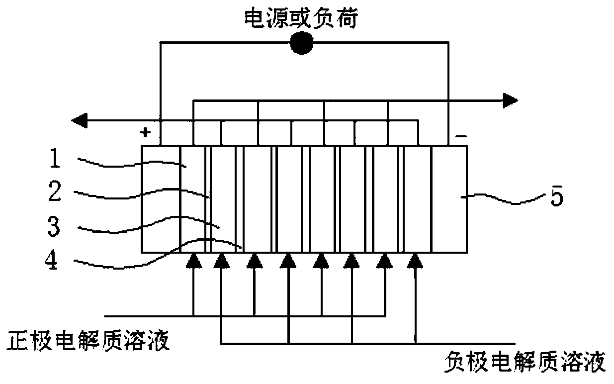
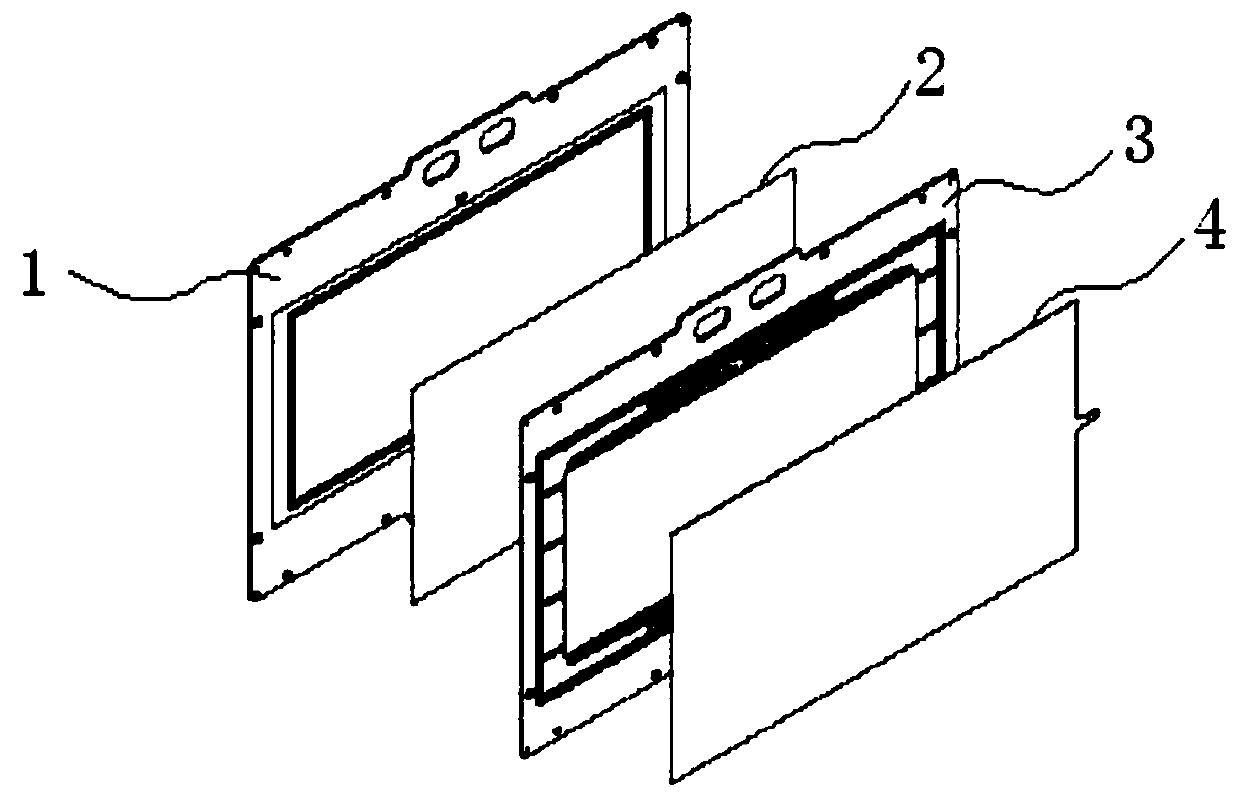
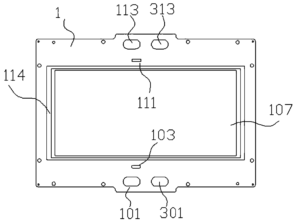

Image

  • Redox flow battery electrode plate frame runner and redox flow battery runner
  • Redox flow battery electrode plate frame runner and redox flow battery runner
  • Redox flow battery electrode plate frame runner and redox flow battery runner

Examples


Embodiment Construction

[0044] Embodiments of the present invention are described in detail below, examples of which are shown in the drawings, wherein the same or similar reference numerals designate the same or similar elements or elements having the same or similar functions throughout. The embodiments described below by referring to the figures are exemplary only for explaining the present invention and should not be construed as limiting the present invention.

[0045] In describing the present invention, it is to be understood that the terms "center", "upper", "lower", "front", "rear", "left", "right", "vertical", "horizontal", The orientations or positional relationships indicated by "top", "bottom", "inner", "outer", etc. are based on the orientations or positional relationships shown in the drawings, and are only for the convenience of describing the present invention and simplifying the description, rather than indicating or implying the It should not be construed as limiting the invention ...


PUM

PropertyMeasurementUnit
areaaaaaaaaaaa
thicknessaaaaaaaaaa
thicknessaaaaaaaaaa

Abstract

The invention discloses a redox flow battery electrode plate frame runner. The redox flow battery electrode plate frame runner comprises an electrode plate frame body, a lower-part electrolyte flowingsharing passage and a flowing limiting runner and also comprises at least one flowing dispersing runner and a flow sharing flowing runner, wherein the lower-part electrolyte flowing sharing passage is arranged at the electrode plate frame body in a penetrating way, the flowing limiting runner communicates with the lower-part electrolyte flowing sharing passage, the sharing flowing runner is connected with a plurality of flowing allocation runners, one end of each of the plurality of flowing allocation runners is connected with the flowing dispersing runner, and the other ends of the pluralityof flowing allocation runners communicate with an electrode cavity. In the redox flow battery electrode plate frame runner proposed by the invention, gradual dispersing flowing to the electrode cavity is employed, an electrolyte simultaneously enters the electrode cavity from the plurality of flowing allocation runners and acts with a porous electrode material, the redox flow speed is reduced, the uniformity of redox flow in the electrode material is improved, full contact of the electrolyte and the electrode material is improved, the surface utilization ratio of the electrode material is improved, the surface reaction polarization of the electrode is reduced, the internal current loss of the battery is reduced, the average power of a battery unit comprising the redox flow battery electrode plate frame runner can reach 300W or above, and the corresponding battery stack power can exceed 30kW.

Description

technical field [0001] The invention relates to the field of new energy, in particular to a flow channel of an electrode plate frame of a liquid flow battery and a flow channel of a flow battery. Background technique [0002] There are three main types of electrical energy storage: mechanical energy storage, electrochemical energy storage and electromagnetic energy storage. Among them, comprehensively measured by indicators such as energy density, efficiency, scale, cycle life and cost, the best technology for the new generation power grid is the liquid phase fluid energy storage battery technology in electrochemical energy storage, and its energy storage density reaches 10- 30Wh / kg, the efficiency is 60%-85%, and the power and capacity can be designed separately, the charging and discharging response is fast, and the application range is wide; it can not only be used for peak shaving and valley filling, but also can be used as a backup power supply or emergency power supply...

Claims


Application Information

Patent Timeline
Patent Type & Authority Applications(China)
IPC IPC(8): H01M8/0258H01M8/18
CPCH01M8/0258H01M8/188Y02E60/50
Inventor 王志升王炳富
Owner SHANGHAI LONGVAULT ENERGY TECH CO LTD
Learn More