
Continuous collision detection method based on spatial subdivision and dynamic bounding box

A collision detection and bounding box technology, applied in the field of collision detection, can solve the problems of time-consuming detection, unverified, unresolved time cost, etc.

Active Publication Date: 2019-07-23
NANCHANG UNIV
View PDF8 Cites 21 Cited by
  • Summary
  • Abstract
  • Description
  • Claims
  • Application Information

AI Technical Summary

Problems solved by technology

However, there are two unavoidable problems in discrete collision detection due to its detection mechanism: (1) When the time interval between two detections is too large, there is a penetration problem in the detection between objects, that is, objects penetrate each other within the detection time interval The transparent algorithm cannot detect the problem that the collision occurs
(2) If the moving speed of the object is fast or the thickness is thin, it may lead to the problem of missed detection, that is, the problem that the collision of the object occurs within the time interval and the problem cannot be detected
However, their scheme does not address the unavoidable time cost of bounding box updates due to mesh topology changes
Li.CQ et al. (A Surface Mass-Spring Model With New Flexion Springs and Collision Detection Algorithms Based on Volume Structure for Real-Time Soft-Tissue Deformation Interaction, IEEE ACCESS, 6, pp:75572-75597, 2018) perfected the traditional continuous Due to the time-consuming shortcomings of collision detection, a hybrid algorithm based on continuous interpolation technology and volume structure detection is proposed
However, the surgical instruments were simplified as spheres in their experiments, so their scheme was not validated in complex scenarios

Method used


Image

  • Continuous collision detection method based on spatial subdivision and dynamic bounding box
  • Continuous collision detection method based on spatial subdivision and dynamic bounding box
  • Continuous collision detection method based on spatial subdivision and dynamic bounding box

Examples


Embodiment Construction

[0050] The invention will be further illustrated by the following examples.

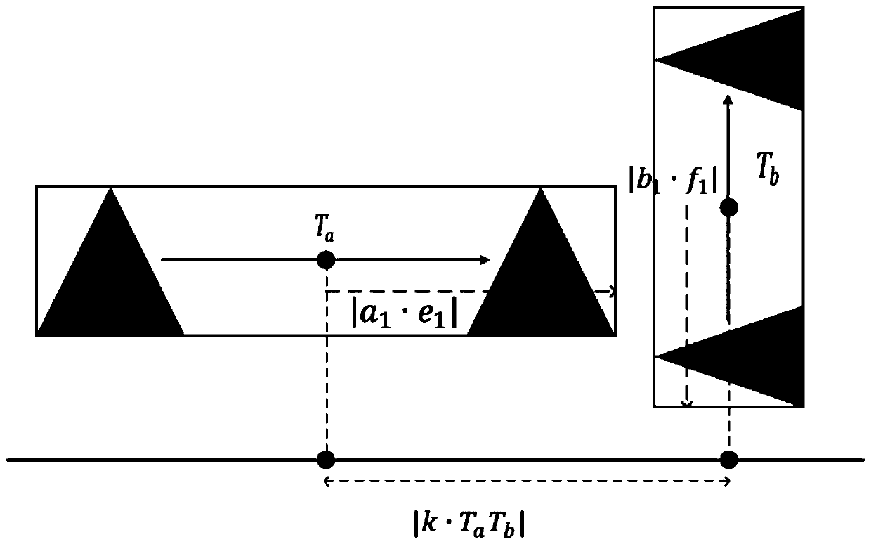
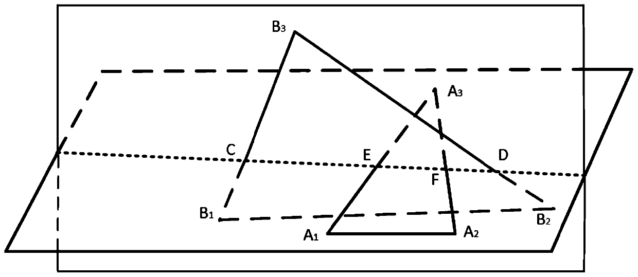
[0051] The virtual surgery system in this paper is composed of virtual scalpel and virtual liver tissue. Among them, the scalpel is composed of 2960 triangular faces, and the liver tissue is composed of 1774 triangular faces. The parameters involved in the method have been verified by experiments, specifically: the length, width, and height of the liver model are 36cm, 25cm, and 25cm, respectively. The length, width and height of the scalpel model are: 21cm, 1.5cm, 1.5cm. The uniform size D of the subspace is 5cm, and the subdivision precision n is 3. In order to make the illustration representative, the specified triangular surface ΔA in the scalpel model and the liver model is respectively 1 B 1 C 1 and ΔA 2 B 2 C 2 Take the steps in this article as an example. Among them, ΔA 1 B 1 C 1 Middle A 1 B 1 C 1 The coordinates are (0.7, 1.3, 12.0), (0.5, 1.2, 12.1), (0.8, 1.5, 12.3). ΔA 2...


PUM


Abstract

The invention discloses a continuous collision detection method based on spatial subdivision and a dynamic bounding box. The continuous collision detection method comprises the steps of constructing avirtual soft tissue model and a virtual instrument model used for collision detection; calculating the space occupied by the moving path of the detection object; constructing dynamic bounding boxes for the moving paths of the objects in the same space, and performing intersection testing on the bounding boxes; determining a position where collision may occur by using a bisection method, and retreating the to-be-detected object from an actual position to a primary collision occurrence position by using a backtracking technology; constructing a hierarchical bounding box for the possible contactobject set and executing bounding box intersection detection; and carrying out an accurate detection step for determining whether the characteristics contained in the child nodes collide. According to the method, the problems of penetration and missed detection of the discrete collision detection method in virtual operation application can be solved, and the calculation efficiency can be greatlyimproved on the premise of ensuring the accuracy.

Description

technical field [0001] The invention belongs to the technical field of collision detection and relates to the problem of collision detection between soft tissues and surgical instruments in virtual operation experiments. Background technique [0002] As an indispensable part in the field of computer graphics and physical simulation, collision detection is a problem that must be solved in the research process of virtual simulation, robot path planning and other topics. In recent years, with the continuous development of computer technology, collision detection has been widely used in computer games, virtual reality and other fields, and has become a hot issue that researchers pay attention to. In virtual surgery, the collision between virtual surgical instrument and human tissue is the basis of deformation calculation and the premise of cutting operation. In the process of deformation calculation and model cutting, the operator has high requirements for collision detection. ...

Claims


Application Information

Patent Timeline
IPC IPC(8): G06T17/20G16H50/50
CPCG06T17/205G16H50/50
Inventor 李春泉潘雨晨胡杜娟刘小平
Owner NANCHANG UNIV
Learn More