Optical scanning device and laser radar

A technology of optical scanning device and diaphragm, which is applied in the optical field, can solve the problems of high sensitivity of receiving detectors, flooding, and large detection blind areas, etc., and achieve the effects of improving receiving and detecting capabilities, reducing scattered light, and reducing detection blind areas

Pending Publication Date: 2019-07-23
SUTENG INNOVATION TECH CO LTD
View PDF0 Cites 6 Cited by
  • Summary
  • Abstract
  • Description
  • Claims
  • Application Information

AI Technical Summary

Problems solved by technology

However, since the micro-electromechanical system itself has reflection and scattering properties for the laser beam, disordered stray light will be generated inside the lidar; and the receiving detector of the lidar is extremely sensitive and responds to these stray light, As a result, the nearby return light signal is submerged in the signal generated by internal stray light, resulting in a large detection blind zone

Method used


Image

  • Optical scanning device and laser radar
  • Optical scanning device and laser radar
  • Optical scanning device and laser radar

Examples


Embodiment Construction

[0025] In order to make the purpose, technical solution and advantages of the present application clearer, the present application will be further described in detail below in conjunction with the accompanying drawings and embodiments. It should be understood that the specific embodiments described here are only used to explain the present application, and are not intended to limit the present application.

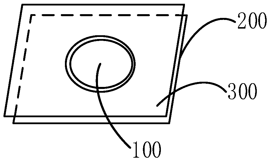
[0026] figure 1 A schematic structural diagram of an optical scanning device provided for an embodiment, such as figure 1 As shown, the device includes: a reflector 100, a reflector base 200 and a light-extinction member 300; the reflector 100 is installed on the reflector base 200, and the light-extinction member 300 is placed in front of the reflector base 200; the reflector 100 is used for The incident light is reflected; the extinction element 300 is used to reduce the scattered light generated by the incident light on the reflector substrate 200 .

[0027] It should...


PUM


Abstract

The application relates to an optical scanning device and a laser radar. The optical scanning device comprises a mirror, a mirror substrate, and an matte member; the mirror is disposed on the mirror substrate, and the matte member is disposed at the front of the mirror substrate; the mirror is used for reflecting an incident light; and the matte member is used for reducing a scattered light generated by the incident light on the mirror substrate. The optical scanning device can greatly reduce the scattered light inside the laser radar, and reduce the detection blind zone caused by the stray light; therefore, the detection capability of the laser radar is greatly improved.

Description

technical field [0001] The present application relates to the field of optical technology, in particular to an optical scanning device and a laser radar. Background technique [0002] With the development of lidar technology, people have higher and higher requirements for the detection performance of lidar. [0003] In solid-state lidar, MEMS is usually used as the core device for scanning. However, due to the reflective and scattering characteristics of the laser beam, the micro-electromechanical system itself will generate disordered stray light inside the lidar; and the receiving detector of the lidar is extremely sensitive and responds to these stray light. As a result, the nearby return light signal is submerged in the signal generated by the internal stray light, resulting in a large detection blind area. Contents of the invention [0004] Based on this, it is necessary to provide an optical scanning device and a laser radar capable of reducing detection blind spot...

Claims


Application Information

Patent Timeline
Patent Type & Authority Applications(China)
IPC IPC(8): G02B26/10G02B26/08G01S7/481
CPCG02B26/105G02B26/0833G01S7/4817G02B5/005G01S17/42Y02A90/10B81B2203/0127G01L9/0041G01L9/0048
Inventor 魏威谭斌
Owner SUTENG INNOVATION TECH CO LTD
Why Eureka
Try Eureka