Visual gas-liquid two-phase flow coupling experiment device

A technology for visualizing gas and experimental devices, applied in the field of two-phase flow experimental systems, can solve the problems of inability to restore gas-liquid two-phase flow, the influence of normal production of gas reservoirs, and inability to study the law of gravity gas-liquid two-phase flow.

Inactive Publication Date: 2019-07-23
TAIYUAN UNIV OF TECH
View PDF7 Cites 2 Cited by
  • Summary
  • Abstract
  • Description
  • Claims
  • Application Information

AI Technical Summary

Problems solved by technology

During the production of gas wells, with the continuous injection of water, water will be produced in the wellbore of the produced fluid. When the gas well produces water, it will have a great impact on the normal production of the gas reservoir, thereby reducing the production capacity of the gas well.
This will seriously affect the implementation of the entire gas field development plan
After investigation and research, most of the existing simulation experiment platforms for gas-liquid two-phase flow study the gas-liquid two-phase flow in a horizontal smooth tube, and cannot study the law of gravity and rough tube wall on gas-liquid two-phase flow. Moreover, in the existing In a small amount of research on gas-liquid two-phase flow experiments in the vertical direction, the gas injection is generally through a slender pipeline, which cannot restore the gas-liquid two-phase flow under actual working conditions. Therefore, it is necessary to design a = visualization gas Liquid two-phase flow coupling experimental device, to carry out similar simulation experiments of gas-liquid two-phase flow in the laboratory

Method used


Image

  • Visual gas-liquid two-phase flow coupling experiment device
  • Visual gas-liquid two-phase flow coupling experiment device
  • Visual gas-liquid two-phase flow coupling experiment device

Examples


Embodiment

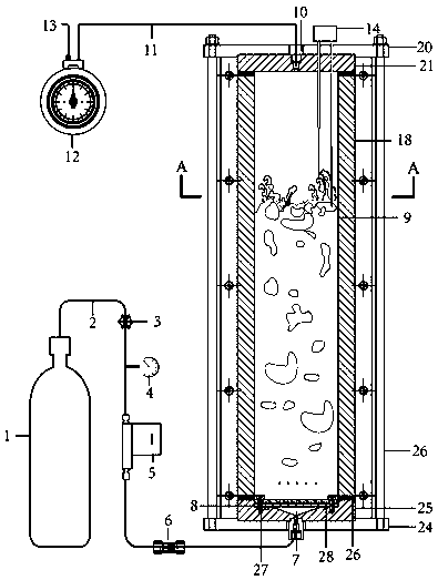
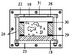
[0015] Example: such as figure 1 and figure 2 As shown, a visual gas-liquid two-phase flow coupling experimental device consists of a channel 9, a gas cylinder 1 for supplying gas, an inlet pipe 2, a pressure regulating valve 3 for adjusting the inlet pressure, a pressure gauge 4, and a gas in the inlet pipe 2 for measuring Flow gas mass flowmeter 5, one-way valve 6, air inlet 7, one-way water barrier 8, channel 9, gas outlet 10, gas outlet pipe 11, flow meter 12 for measuring gas flow in the gas outlet pipe 11, outlet 13 And the double-headed conductivity probe 14 is formed.

[0016] The gas cylinder 1 , the pressure regulating valve 3 , the gas mass flow meter 5 and the one-way valve 6 are sequentially arranged on the intake pipe 2 .

[0017] The pressure gauge 4 is arranged on the inlet pipe 2 between the pressure regulating valve 3 and the gas mass flow meter 5 .

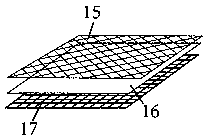
[0018] image 3 As shown, the one-way water-proof layer 8 is located at the bottom of the channel 9, and...


PUM


Abstract

The invention relates to the technical field of a two-phase flow experiment system, in particular to a visual gas-liquid two-phase flow coupling experiment device. The device mainly consists of a gascylinder, a gas inlet tube, a pressure regulation valve, a pressure gage, a gas quality flowmeter, a check valve, a gas inlet, a one-way water-proof layer, a channel, a gas outlet, a gas outlet tube,a flowmeter and an outlet, wherein the pressure gage is arranged on the gas inlet tube between the pressure regulation valve and the gas quality flowmeter; the one-way water-proof layer is positionedon the bottom of the channel and consists of a metal screen plate, a waterproof air-permeable filter membrane and a metal supporting screen plate; and the channel consists of a rock plate, an organicglass plate, an upper pressing plate and a lower pressing plate. By use of the visual gas-liquid two-phase flow coupling experiment device disclosed by the invention, a gas-liquid two-phase flow simulation experiment under tube walls of different sizes and different roughness levels under a gravity condition can be realized, a one-way water-proof device is designed, and gas can be evenly injectedfrom the bottom of the channel.

Description

technical field [0001] The invention relates to the technical field of two-phase flow experimental systems, in particular to a visual gas-liquid two-phase flow coupling experimental device. Background technique [0002] In the process of gas field development, when the gas reservoirs are first exploited, due to the large amount of gas reservoirs at the bottom of the well, the water production is small and the pressure is high. As the pressure of the gas-producing formation at the bottom of the well continues to drop, some gas fields use the method of water injection to extract the gas in the gas wells. . During the production of gas wells, with the continuous injection of water, water will be produced in the wellbore of the produced fluid. When the gas well produces water, it will have a great impact on the normal production of the gas reservoir, thereby reducing the productivity of the gas well. This will seriously affect the implementation of the entire gas field developm...

Claims


Application Information

Patent Timeline
Patent Type & Authority Applications(China)
IPC IPC(8): G01N11/00G01M10/00
CPCG01N11/00G01M10/00
Inventor 胡胜勇陈云波冯国瑞廖奇高扬郝国才
Owner TAIYUAN UNIV OF TECH
Why Eureka
Try Eureka