Water tank and water removing structure of water tank

A water tank and card slot technology, which is used in water supply installations, indoor sanitary pipe installations, buildings, etc., can solve the problems of difficult repair of defective products, concave and convex surfaces affecting water removal, and many defective products, and achieves good anti-corrosion and mechanical properties. The effect of simplifying the process flow and reducing the production cost

Pending Publication Date: 2019-07-23
张文军
View PDF0 Cites 0 Cited by
  • Summary
  • Abstract
  • Description
  • Claims
  • Application Information

AI Technical Summary

Problems solved by technology

[0003] One of the existing structures on the market, the traditional sink water removal structure, is to directly weld the threaded metal hollow joint around the water outlet of the sink body to form a simple seamless water removal structure. This structure is complicated to process and requires professional expertise. Welding technicians can process, manual welding has poor consistency, many defective products, and defective products are difficult to repair. There are welding spots and welding traces at the welding place, which need to be polished. Due to the influence of high-temperature welding, around the water outlet or the entire inner tank Deformation, resulting in concave and convex surfaces that affect water removal, poor product visibility and manufacturing process, high cost, and unable to place a filter;
[0004] Another traditional sink water removal structure on the market is a "T"-shaped sealing water removal structure formed by flat pressing the sealing rubber ring, that is, the cut section of the inner sealing component of this structure is in a "T" shape: That is to say, punch a groove hole vertically with a punching machine for the sink hole, and press the sealing rubber ring on the front or back of the groove hole of the sink to achieve sealing by applying pressure to the inner seal assembly and the outer seal assembly of the T-shaped structure. Disadvantages: 1. Due to The mold is punched vertically by the punching machine, and grooves are formed at the outlet hole of the inner groove, and the root of the groove will form an R angle. In order to avoid the R angle, the diameter of the inner seal component must be smaller than the diameter of the concave groove to be compatible with the concave groove. The installation is consistent. After the installation is completed, the inner sealing component is on the concave groove edge of the inner groove, resulting in a seam, which is easy to accumulate dirt and is not beautiful. 2. The vertical punching force is large and easy to damage the processing equipment. 3. Due to the vertical punching of the concave groove (counterbore) , the depth of the counterbore is limited (too deep is easy to crack), so it is difficult to make the inner seal component lower than the bottom surface of the inner tank after installation, and it is easy to cause free water removal. 4. Due to the limitation of the depth of the groove, the inner seal The pressure part of the component, that is, the top wall thickness cannot be processed too thick. If it is too thick, it will be higher than the bottom plane of the inner groove and affect the water removal; When the installation is carried out, the sealing rubber ring is prone to irregular sliding when the force is applied. If the force is too large, it will slide to the edge of the concave groove and be exposed outside, causing the seal to fail. If the force is too small, it is easy to loosen. The method of adding sealing rings on both sides of the front and back reduces the pressure area of ​​the direct contact of the metal; it is difficult to effectively fit and fix the structural parts in a suspended state, and the structural parts are in a loose state. 6. This structure adopts compression sealant The method of making the sealing rubber ring pressurized to achieve sealing, but the sealing rubber ring is subject to long-term pressure fatigue, aging or other environmental factors, which is prone to water leakage. The sealing rubber ring is directly in contact with the liquid, and the overall structure has poor corrosion resistance and mechanical properties. Poor; 7. The upper end of the inner seal assembly is too thin to install a drain funnel; 8. The upper end of the inner seal assembly is too thin to install a filter slot. In the through hole, the fixed part is stuck above the inner seal, which is higher than the bottom plane of the inner tank, which affects the appearance and prevents water removal, or makes a complicated drip device. Since the water removal hole of the inner seal structure is small in diameter, the Install a smaller filter leaking net, the solid part of the filtering net is blocked, and the actual water removal area is less than 1 / 2 of the hole. The water removal efficiency is very low. 8. Because the upper wall thickness of the inner sealing component is too thin, the inner wall cannot be installed It is difficult to install because of the force card slot. 9. Since the sealing rubber ring also acts as a rubber gasket in this structure, when the two sealing rubber ring pads are in the structural parts, the structural parts cannot be screwed together by force. If it is fully matched, a large position error will occur after the whole is completed (because the gap between the rubber pads between the two structural parts cannot be consistent), which will affect the accuracy of the docking installation with the outer box pipeline

Method used


Image

  • Water tank and water removing structure of water tank
  • Water tank and water removing structure of water tank
  • Water tank and water removing structure of water tank

Examples


Embodiment Construction

[0022] The following will clearly and completely describe the technical solutions in the embodiments of the present invention with reference to the accompanying drawings in the embodiments of the present invention. Obviously, the described embodiments are only some, not all, embodiments of the present invention. Based on the embodiments of the present invention, all other embodiments obtained by persons of ordinary skill in the art without making creative efforts belong to the protection scope of the present invention.

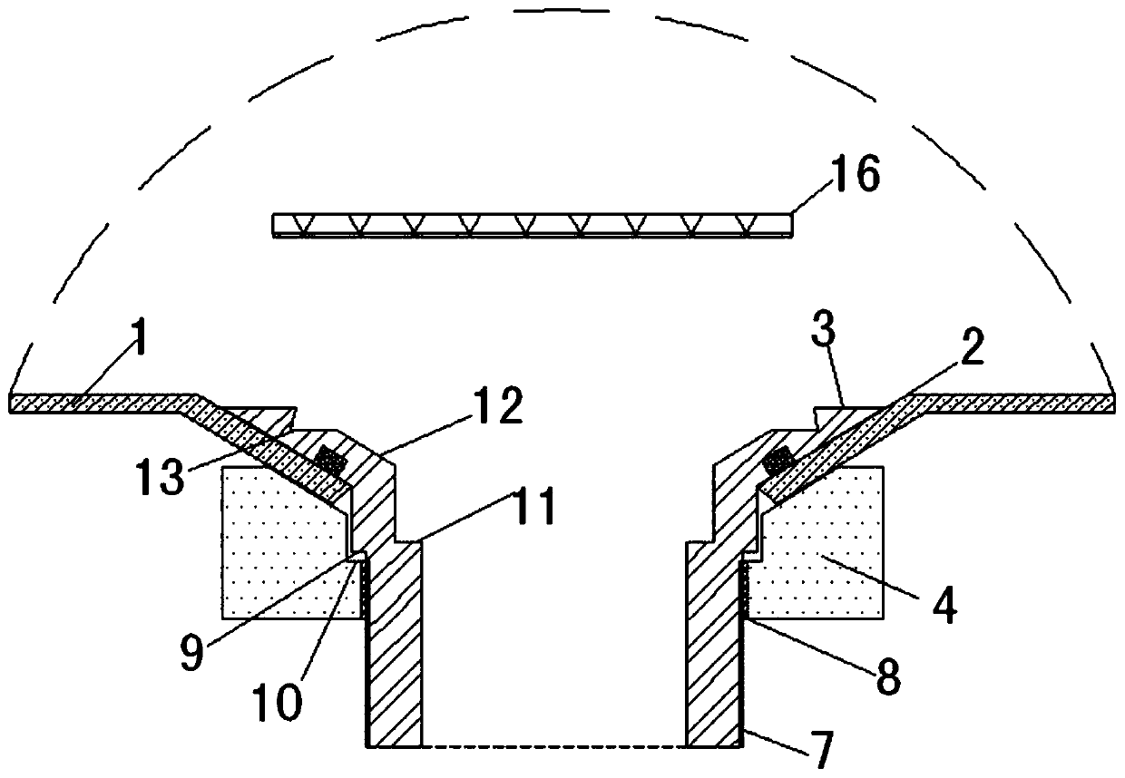
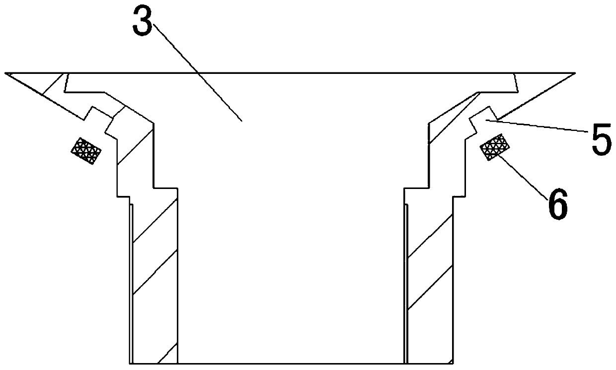
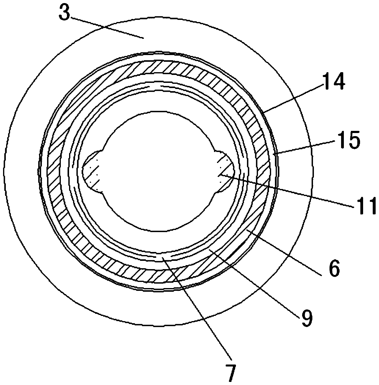
[0023] see Figure 1-5 , the present invention provides a technical solution: a water tank and a water removal structure of the water tank, including a water tank body 1, a chute hole 2, an inner sealing component 3, an outer sealing component 4, a sealing ring slot 5, and a sealing rubber ring 6 , external thread connection part 7, internal thread connection part 8, first avoidance step 9, second avoidance step 10, afterburner wrench slot 11, drain funnel 12,...


PUM


Abstract

The invention discloses a water tank and a water removing structure of the water tank. The water tank and the water removing structure of the water tank comprise a water tank body, a chute hole, an inner sealing assembly, an outer sealing assembly, a sealing ring clamping groove, a sealing rubber ring, an external thread connecting part, an internal thread connecting part, a first empty avoiding step, a second empty avoiding step, a forcing wrench clamping groove, a water removing funnel, a filter network clamping groove, a clamping groove clamping hook, a clamping groove platform and a filternet, wherein the chute hole is formed in the center of the water removing surface of the bottom end of the water tank body and is in a V shape. According to the water tank and the water removing structure of the water tank, the arrangement of the chute hole in the water tank body enables the water tank to be drained more quickly and conveniently, and in coordination with the arrangement of the Y-shaped water removing structure, a traditional "T" shaped sealing mode in which the sealing rubber ring is pressed is changed into a "Y" shaped sealing mode of filling the sealing rubber ring; the sealing thought and method are essentially reformed, and the "Y" type structural member conforms to the mechanical principle and is firm and strong enough, the performance is good, the functions are multiple, the installation is easy, and the visual effect is good.

Description

technical field [0001] The invention relates to the technical field of water tanks, in particular to a water tank and a water removal structure for the water tank. Background technique [0002] Sink refers to an open liquid storage tank, or a liquid storage container with a detachable cover on one side. Among them, household wash basins and special cleaning tanks can all belong to the type of sink, and the water storage tower belongs to the type of liquid storage container; [0003] One of the existing structures on the market, the traditional sink water removal structure, is to directly weld the threaded metal hollow joint around the water outlet of the sink body to form a simple seamless water removal structure. This structure is complicated to process and requires professional expertise. Welding technicians can process, manual welding has poor consistency, many defective products, and defective products are difficult to repair. There are welding spots and welding traces a...

Claims


Application Information

Patent Timeline
Patent Type & Authority Applications(China)
IPC IPC(8): E03C1/182E03C1/22E03C1/264
CPCE03C1/182E03C1/22E03C1/264
Inventor 张文军
Owner 张文军
Why Eureka
Try Eureka