Forming welding equipment for I-steel production

A technology of welding equipment and I-beam, which is applied in the direction of welding equipment, auxiliary welding equipment, welding/cutting auxiliary equipment, etc., which can solve problems such as the limitation of the flip angle range, the inability to accurately adjust the welding angle, and structural limitations, so as to avoid potential safety hazards Effect

Active Publication Date: 2019-07-23
山东华泰钢结构工程有限公司
View PDF10 Cites 4 Cited by
  • Summary
  • Abstract
  • Description
  • Claims
  • Application Information

AI Technical Summary

Problems solved by technology

[0004] When the above-mentioned patent is turned over by the working plate, due to its structural limitation, the turning angle range is limited, and the welding angle cannot be adjusted accurately, thus affecting the production quality of the I-beam

Method used


Image

  • Forming welding equipment for I-steel production
  • Forming welding equipment for I-steel production
  • Forming welding equipment for I-steel production

Examples


Embodiment Construction

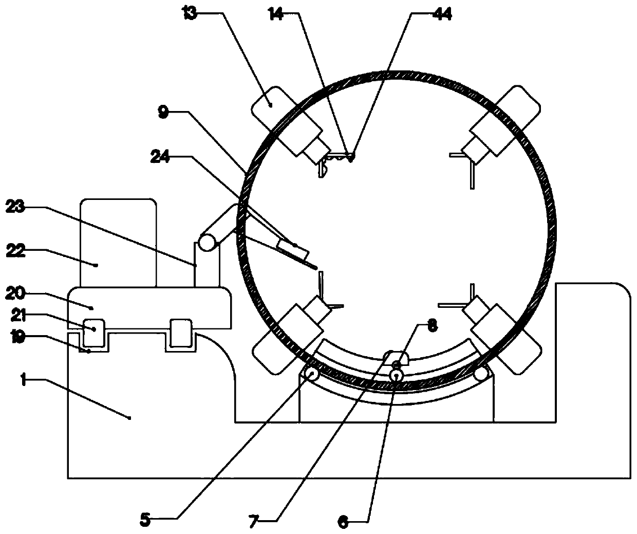
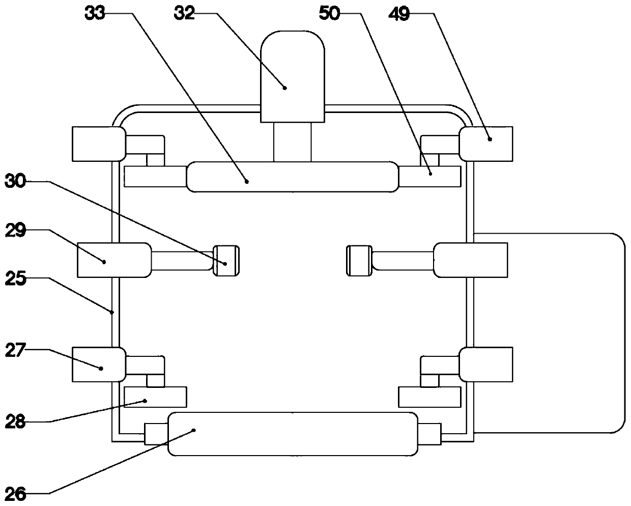
[0023] The present invention is specifically described below in conjunction with accompanying drawing, as Figure 1-5 shown.

[0024] In this embodiment, the model of controller 41 is CPM1A-DA002 model, and the signal output terminal of controller 41 is connected with drive motor 7, hydraulic pump 46, drive wheel 21, welder one 22, welder two 42, drive roller One 26, telescopic rod one 27, telescopic rod two 29, the signal input end of suction pump 39 are electrically connected, the power output end of controller 41 is connected with drive motor 7, hydraulic pump 46, drive wheel 21, welder one 22, Welding machine two 42, driving roller one 26, telescopic rod one 27, telescopic rod two 29, and the power supply input end of suction pump 39 are electrically connected.

[0025] The invention of this application lies in the structural design of the full-angle overturn welding device, which is combined with the attached figure 2 and 5 The full-angle flip welding device drives th...


PUM


Abstract

The invention discloses forming welding equipment for an I-steel production. The forming welding equipment comprises a rectangular base, wherein a welding slag collecting device is arranged above therectangular base, a full-angle turnover welding device is arranged on the upper surface of the rectangular base, the I-steel forming device is arranged at one end of the I-shaped steel turnover device; the full-angle turnover welding device drives a rotating drum through a motor, the rotating drum drives the I-steel to rotate, steel plates are fixed through the combined action of the telescopic rods and the hydraulic cylinders, and the steel plates are formed and welded through the action of the welding machine. The forming welding equipment has the beneficial effects of being simple in structure and high in practicability.

Description

technical field [0001] The invention relates to the related field of I-beam processing, in particular to a forming welding equipment used for I-beam production. Background technique [0002] The production process of large I-beams is basically to cut the entire steel plate into webs or flange plates in batches, then assemble them, and finally weld them with a welding machine. The I-beam needs to be fully welded during welding. Due to the weld distribution and welding process, when welding a complete I-beam, the I-beam needs to be turned over to keep the different welds in an upward posture. [0003] In the patent No. 201710167054.0, a full-angle flip welding device, the workpiece is fixed on the work plate after the electromagnet is energized, and the first hydraulic cylinder is opened to push the welding torch fixing seat and the first welding torch moves to the workpiece. The support can be set as The lifting platform realizes the welding seam at the same height. The firs...

Claims


Application Information

Patent Timeline
IPC IPC(8): B23K37/047B23K37/00
CPCB23K37/00B23K37/047
Inventor 郑肖
Owner 山东华泰钢结构工程有限公司
Why Eureka
Try Eureka