Synchronous clamping and turnover mechanism

A technology of clamping mechanism and flipping mechanism, which is applied in the direction of conveyors, conveyor objects, transportation and packaging, etc. It can solve problems such as clamping instability, clamping failure, and falling of the clamped object, and achieve flexible flipping and clamping firm effect

Pending Publication Date: 2020-04-17
KUNMING XUBANG MACHINERY
View PDF1 Cites 3 Cited by
  • Summary
  • Abstract
  • Description
  • Claims
  • Application Information

AI Technical Summary

Problems solved by technology

When the cylinder is used as the driving element, there are the following disadvantages: 1) Due to the compressibility of the gas, there are often safety accidents such as instability of the clamping and sliding down or clamping failure; 2) If the gas source is interrupted during use, it will also cause The clamped object falls directly, causing a safety accident
Another driving method is hydraulic cylinder drive. For example, the unloading machine described in the invention patent CN207844512U uses hydraulic cylinders to realize clamping and turning. This unloading machine has the following disadvantages: 1) The hydraulic cylinder is prone to leakage when it runs for a long time. Pollution to the clamped items or raw materials; 2) The hydraulic system is more complex and costly; 3) It is difficult to synchronize multiple driving mechanisms

Method used


Image

  • Synchronous clamping and turnover mechanism
  • Synchronous clamping and turnover mechanism
  • Synchronous clamping and turnover mechanism

Examples


Embodiment Construction

[0018] The present invention will be further described below in conjunction with the accompanying drawings.

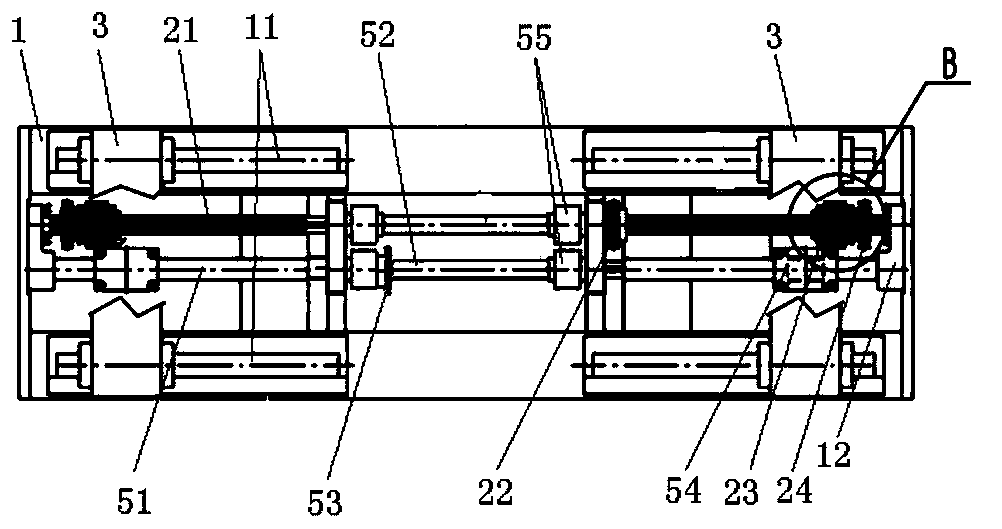
[0019] The synchronous clamping and overturning mechanism provided by the present invention includes a support 1, a clamping mechanism 3, a clamping drive mechanism 5, a turning mechanism 4 and a turning drive mechanism 2 are arranged on the support 1, wherein: the clamping mechanism 3 is set as The two facing ones, and the two clamping mechanisms 3 are all slidably connected to the bracket 1, and are connected to the same clamping drive mechanism 5, and each clamping mechanism 3 is rotatably connected to the corresponding flipping mechanism 4, and the two flipping mechanisms Mechanisms 4 are all connected to the same overturning drive mechanism 2;

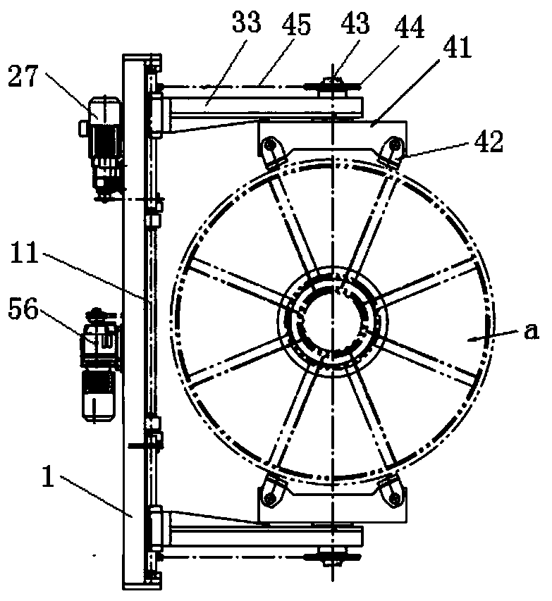
[0020] Described clamping mechanism 3 comprises vertical plate 31, is arranged on the clamp arm 33 that protrudes outwards on the front of vertical plate, is arranged on the slide block 32 of the upper and lower end of ver...


PUM


Abstract

The invention provides a synchronous clamping and turnover mechanism, which comprises a support. The mechanism is characterized in that clamping mechanisms, a clamping driving mechanism, turnover mechanisms and an turnover driving mechanism are arranged on the support, wherein the number of the clamping mechanisms is two, the two clamping mechanisms are both connected to the support in a sliding mode and connected with the same clamping driving mechanism; each clamping mechanism is rotationally connected with the corresponding turnover mechanism; and the two turnover mechanisms are both connected with the same turnover driving mechanism. The two clamping mechanisms are driven by the same clamping driving mechanism to slide in a face-to face manner to synchronously clamp an object, and movein a back-to-back manner to synchronously loosen clamping of the object; and two turnover mechanisms are driven by the same turnover driving mechanism to overturn the clamped object, so that clampingis firm and reliable, turnover is flexible, and no pollutant is generated; and the synchronous clamping and turnover mechanism is suitable for clamping various articles, especially for clamping of amedicine extraction basket and turnover of medicines or extracts on the turnover face.

Description

technical field [0001] The invention provides a mechanism for clamping and overturning synchronously, in particular to a mechanism for clamping and overturning objects, which belongs to the technical field of mechanical design and manufacture. Background technique [0002] The article clamping and turning mechanisms involved in the prior art mainly realize clamping through air cylinders or hydraulic cylinders, and use turning shafts to realize turning and unloading. When the cylinder is used as the driving element, there are the following disadvantages: 1) Due to the compressibility of the gas, there are often safety accidents such as the clamping instability resulting in sliding or clamping failure; 2) If the gas source is interrupted during use, it will also cause The clamped object falls directly, causing a safety accident. Another driving method is hydraulic cylinder drive. For example, the unloading machine described in the invention patent CN207844512U uses hydraulic ...

Claims


Application Information

Patent Timeline
Patent Type & Authority Applications(China)
IPC IPC(8): B65G47/90B65G47/38
CPCB65G47/38B65G47/904B65G2201/0235
Inventor 王晓耕郑治义王润哲
Owner KUNMING XUBANG MACHINERY
Why Eureka
Try Eureka