
20KW laser cutting machine

A laser cutting machine, 20KW technology, applied in the direction of laser welding equipment, welding equipment, metal processing equipment, etc., can solve the problems that can only be fixed on the machine body, the dust removal effect of the exhaust mechanism is not obvious, and the size of the laser generator is large.

Inactive Publication Date: 2019-07-23
PENTA CHUTIAN LASER (WENZHOU) CO LTD
View PDF0 Cites 0 Cited by
  • Summary
  • Abstract
  • Description
  • Claims
  • Application Information

AI Technical Summary

Problems solved by technology

Depending on the power of the laser cutting machine, the layout of the optical path is also different. For a laser cutting machine with a small power meter, the laser generator is relatively small in size and can move synchronously with the cutting head to ensure a constant beam formation. For laser cutting machines with high power, the size of the laser generator is generally large, so it can only be fixed on the machine body, and the cutting head moves repeatedly. Therefore, in the process of cutting, the laser generator and the cutting head must be connected The optical fiber cables will move with the movement of the cutting head and appear scattered, which will interfere with the operation of other components. In addition, the laser cutting machine will generate a lot of dust during the metal cutting process, so a ventilation mechanism is needed to discharge the dust from the working area. At present, the overall exhaust mechanism is generally used. However, due to the large working area, the dust removal effect of the overall exhaust mechanism is not significant. It cannot meet the requirements in occasions with high requirements for the working environment, and needs to be improved.

Method used


Image

  • 20KW laser cutting machine
  • 20KW laser cutting machine
  • 20KW laser cutting machine

Examples


Embodiment Construction

[0023] The present invention will be further described with reference to the accompanying drawings.

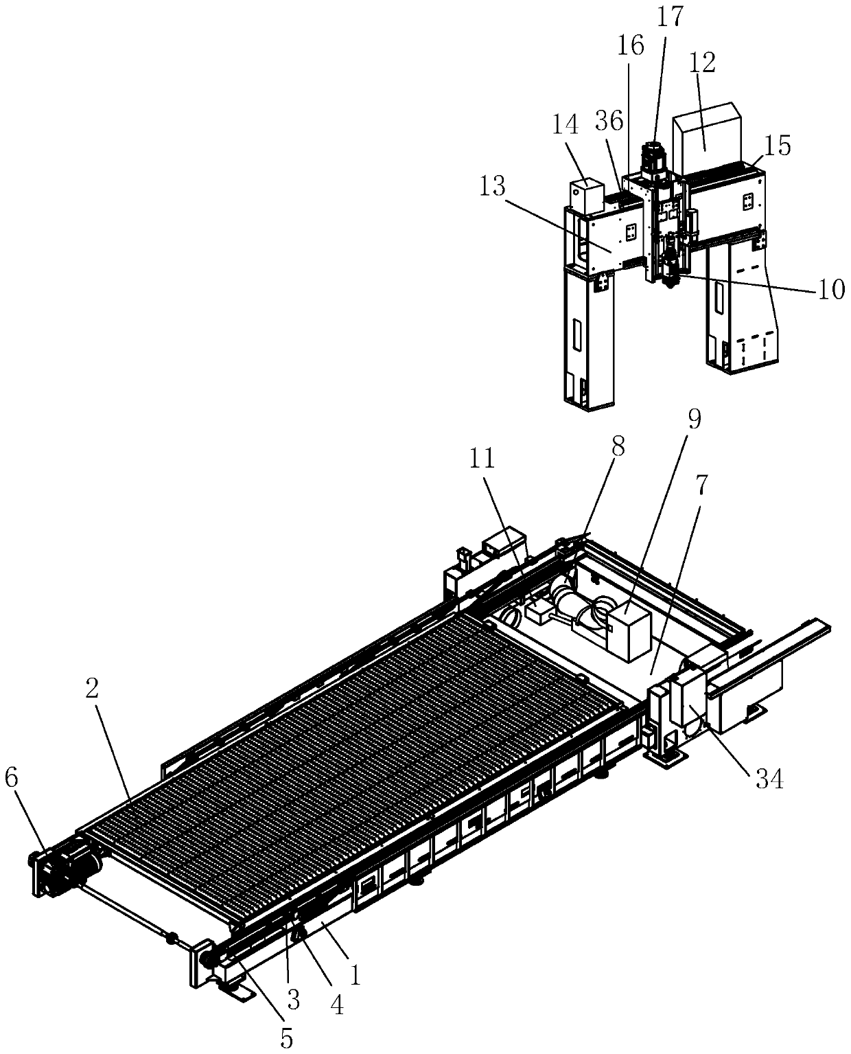
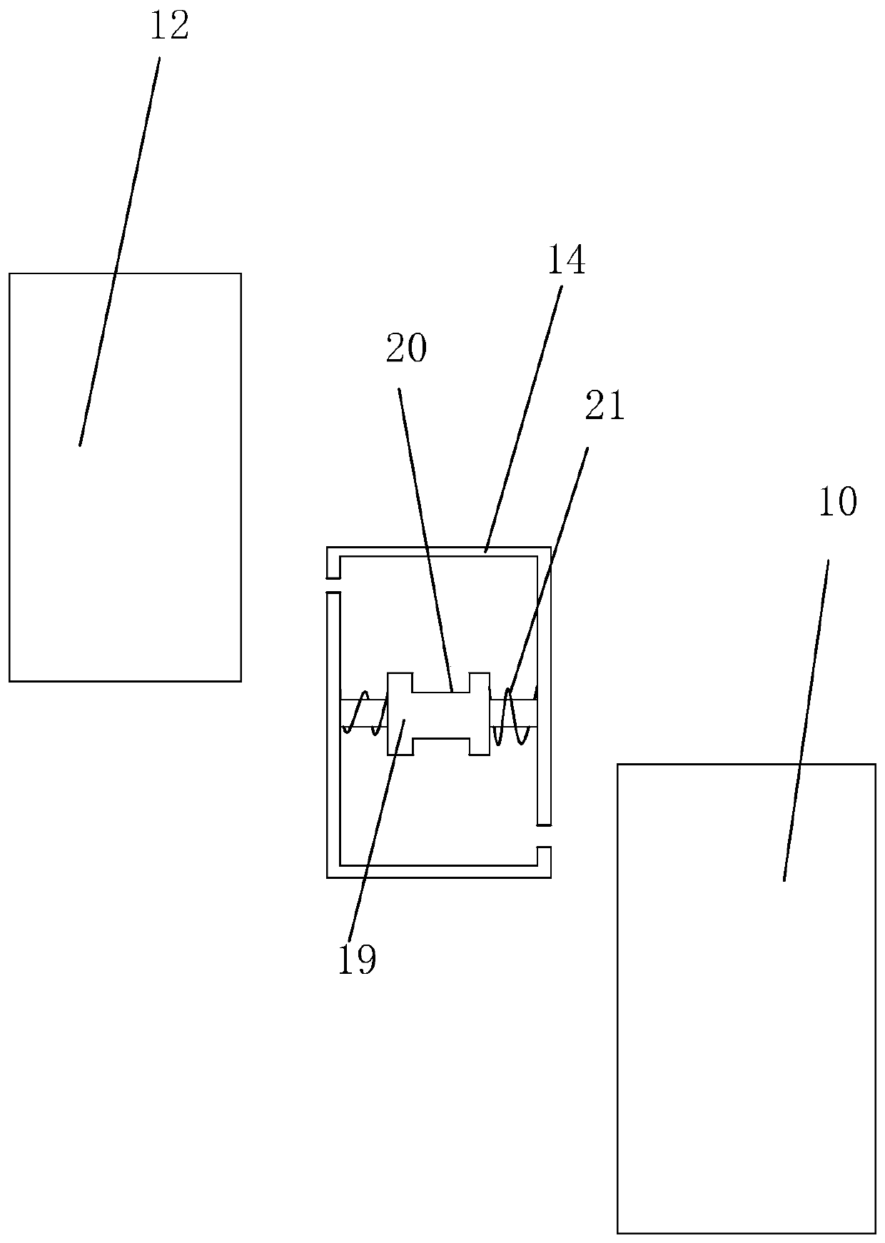
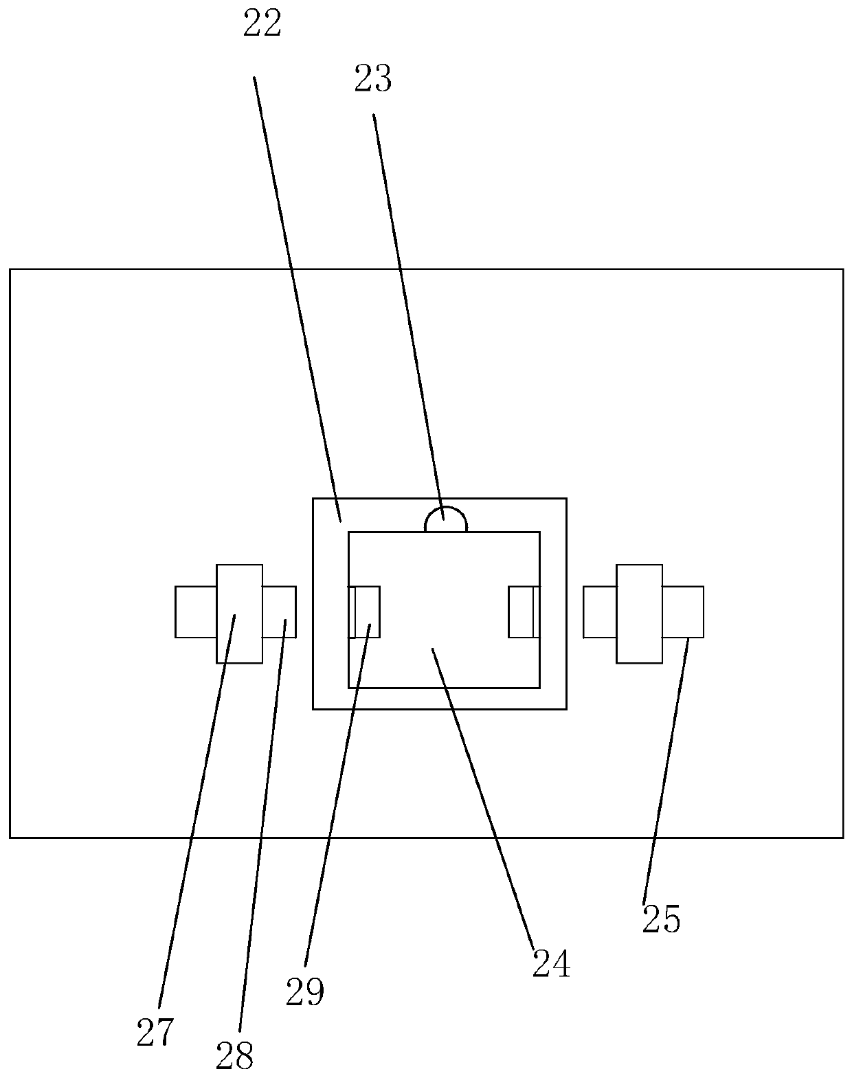
[0024] A 20KW laser cutting machine, such as Figure 1-Figure 5 As shown, including a machine tool 1, a triangular bearing plate 2 is arranged on the top of the machine tool 1, and both sides of the bearing plate 2 are fixedly connected with a plurality of fixed rods 3, and each fixed rod 3 is sleeved with a rotating shaft 4. The rotating shaft 4 and the conveyor belt 5 are in a fixed connection, and the rotating shaft 4 will move along with the conveyor belt 5 without rotation. A plurality of the rotating shafts 4 are socketed with the same conveyor belt 5, and one end of the conveyor belt 5 is provided with a first motor 6 that drives the conveyor belt 5 to rotate, and the machine tool 1 is fixedly connected with a concave plate 7 below the bearing plate 2 , the concave plate 7 is pierced with a bellows 8 connected to the exhaust fan 24, and one end of the bellows 8 in the ...


PUM


Abstract

The invention relates to a 20KW laser cutting machine. The laser cutting machine comprises a machine tool, a bearing plate, a fixed rod, a rotating shaft, a conveying belt and a first motor; the machine tool is fixedly connected with a concave plate located below the bearing plate, the concave plate is provided with a corrugated pipe in a penetrating manner, the corrugated pipe is connected with an exhaust fan, the end, located in the concave plate, of the corrugated pipe is detachably connected with an L plate, the concave plate is provided with an air cylinder fixedly connected with the L plate, a laser generator is arranged in the middle of the machine tool, a cross beam is arranged in the middle of the machine tool, a containing box used for placing an optical fiber cable is arranged on the upper surface of the cross beam, a drawing-in device for drawing in the optical fiber cable is arranged in the containing box, the laser generator is connected with a cutting head capable of sliding on the cross beam, and an opening in the end, away from the exhaust fan, of the corrugated pipe faces the cutting head. The machine has the advantage that under the condition that the laser generator is fixed to the machine tool, moving of the cutting head does not cause optical fibre cable scattered distribution.

Description

technical field [0001] The invention relates to the technical field of laser cutting equipment, in particular to a 20KW laser cutting machine. Background technique [0002] Laser cutting technology is to focus the laser beam so that it has enough high temperature and then cut the sheet. The laser cutting machine is generally controlled by a numerical control system, and the cross slide rail is used to enable the cutting head to move in any direction relative to the surface to be cut. For this reason, the cutting head of the laser cutting machine is generally slid on a beam. Depending on the power of the laser cutting machine, the layout of the optical path is also different. For a laser cutting machine with a small power meter, the laser generator is relatively small in size and can move synchronously with the cutting head to ensure a constant beam formation. For laser cutting machines with high power, the size of the laser generator is generally large, so it can only be fi...

Claims


Application Information

Patent Timeline
IPC IPC(8): B23K26/38B23K26/70
CPCB23K26/38B23K26/70B23K26/702B23K26/703
Inventor 吴让大杨忠明李正张业芝
Owner PENTA CHUTIAN LASER (WENZHOU) CO LTD
Learn More