Self-anchored suspension bridge main cable tightening cable pretensioning device and method

A self-anchored suspension bridge and main cable technology, which is applied in the field of suspension bridge cable tightening, can solve the problems of affecting construction progress, scattered, low efficiency, etc., and achieve the effect of preventing scattered distribution and improving binding efficiency

Active Publication Date: 2022-05-20
中国铁建投资集团有限公司
View PDF6 Cites 0 Cited by
  • Summary
  • Abstract
  • Description
  • Claims
  • Application Information

AI Technical Summary

Problems solved by technology

[0004] However, due to the scattered cables after the completion of traction, the efficiency of manual fixing of the cables is low, which will directly affect the construction progress

Method used


Image

  • Self-anchored suspension bridge main cable tightening cable pretensioning device and method
  • Self-anchored suspension bridge main cable tightening cable pretensioning device and method

Examples


Embodiment 1

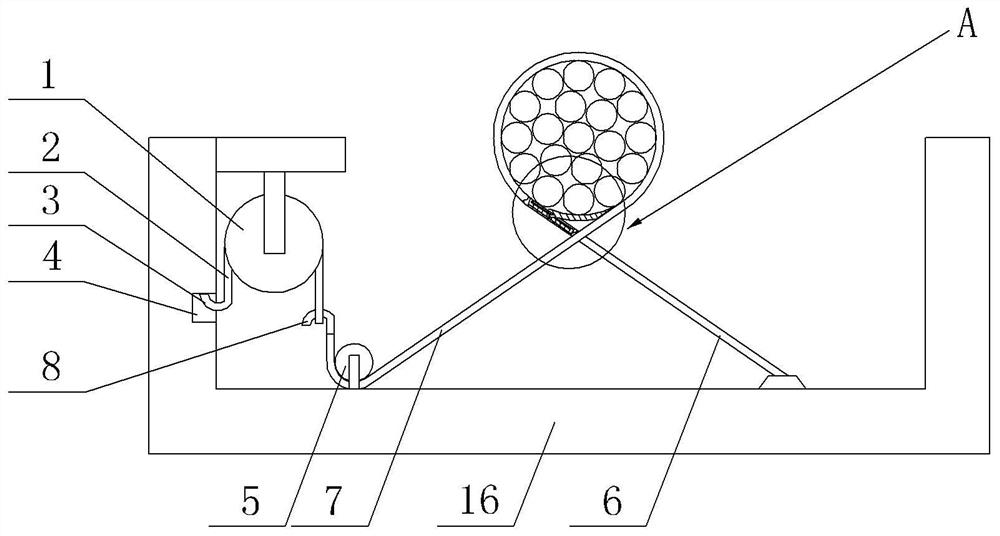
[0029] Embodiment one is basically as attached figure 1 , 2 Shown: as figure 1 The shown self-anchored suspension bridge main cable tensioning cable pretensioning device includes several pretensioning mechanisms and chain hoists 1 . Chain block 1 can choose Hsz type. Chain block 1 includes chain 2 and two hooks 3. The hooks 3 are welded to both ends of the chain 2. There is a gap 4 on the catwalk 16. The hook 3 on the left can Clamped in the gap 4, the catwalk 16 is also rotatably equipped with a pulley 5.

[0030] Each pretensioning mechanism all comprises the first pretensioning rope 6 and the second pretensioning rope 7, the right end of the first pretensioning rope 6 is welded with catwalk 16, the left end of the second pretensioning rope 7 is welded with hook 8, the second After the left end of the pre-tightening rope 7 walks around the pulley 5, the hook 8 is detachably connected with the suspension hook 3 .

[0031] Such as figure 2 As shown, the left end of the f...

Embodiment 2

[0038] Such as figure 2 As shown, the arc-shaped plate 11 is Y-shaped, and the right end of the arc-shaped plate 11 fits the middle part of the second pretensioning rope 7, and the left end of the arc-shaped plate 11 includes a first branch 14 and a second branch 15, and the first branch 14 is rotationally connected with the first pretensioning rope 6 at the slot 10 through a pin shaft, and the second branch 15 can be offset against the first pretensioning rope 6 . In addition if figure 1 The side wall of the pulley 5 shown has a groove, and the second pretensioning rope 7 is located in the groove.


PUM


Abstract

The invention relates to the field of cable tightening of suspension bridges, in particular to a self-anchored suspension bridge main cable tensioning device and method. The pretensioning device includes several pretensioning mechanisms, and each pretensioning mechanism includes a first pretensioning rope and a second pretensioning rope One end of the first pretension rope is fixedly connected to the catwalk, one end of the second pretension rope is detachably connected to the catwalk; the other end of the first pretension rope is provided with a card slot, and the other end of the first pretension rope The side wall of the side wall is provided with a through groove connected with the card groove, and an arc-shaped plate is rotatably connected to the through groove, the other end of the second pre-tension rope can be inserted into the slot, and one end of the arc-shaped plate can be connected with the second pre-tension rope The other end of the second pre-tightening rope can be locked against the other end of the arc plate; the pre-tightening method includes step 1: tighten the pre-tightening; step 2: support the cable at the bottom; Limit the degree of pretension; Step 4: Locate the position of the main cable. When the technical solution is adopted, it is convenient to quickly fix the cables.

Description

technical field [0001] The invention relates to the field of cable tightening of suspension bridges, in particular to a cable pretensioning device and method for main cables of self-anchored suspension bridges. Background technique [0002] The catwalk is a linear temporary construction aerial platform under the main cable of the suspension bridge and parallel to the main cable, so that construction workers can complete the construction tasks such as the installation of the main cable on the catwalk. [0003] The main cable is composed of several strands of cables. After the cable is pulled, it is necessary to manually lock the cable with a hoop, so that several strands of cables are combined to form the main cable. [0004] However, due to the looseness of the cable traction after completion, the efficiency of manually fixing the cables is low, which will directly affect the construction progress. Contents of the invention [0005] The purpose of the present invention is...

Claims


Application Information

Patent Timeline
Patent Type & Authority Patents(China)
IPC IPC(8): E01D21/00E01D19/16E01D11/02
CPCE01D21/00E01D19/16E01D11/02Y02E10/728
Inventor 杨晓华刘晓剑李新民段向虎毛东晖王宏伟刘玉成陈可华
Owner 中国铁建投资集团有限公司
Why Eureka
Try Eureka