
Shield tunnel surface image calibration method, splicing method and splicing system

A surface image and shield tunneling technology, applied in image analysis, image conversion, image data processing, etc., can solve the problems of unsuitable surface structure, high cost of splicing, complicated calibration, etc., and achieve short splicing time and conform to vision Effects, Calibration Effects with simple operation

Active Publication Date: 2019-07-19
HUAZHONG UNIV OF SCI & TECH
View PDF7 Cites 8 Cited by
  • Summary
  • Abstract
  • Description
  • Claims
  • Application Information

AI Technical Summary

Problems solved by technology

[0005] Aiming at the defects of the prior art, the purpose of the present invention is to solve the technical problems of the prior art that the calibration is complicated, not suitable for curved surface structures, requires a large number of cameras, leads to high splicing costs, and is not suitable for curved surface structures

Method used


Image

  • Shield tunnel surface image calibration method, splicing method and splicing system
  • Shield tunnel surface image calibration method, splicing method and splicing system
  • Shield tunnel surface image calibration method, splicing method and splicing system

Examples


Embodiment Construction

[0039] In order to make the object, technical solution and advantages of the present invention clearer, the present invention will be further described in detail below in conjunction with the accompanying drawings and embodiments. It should be understood that the specific embodiments described here are only used to explain the present invention, not to limit the present invention.

[0040] Both the image mosaic method and the image calibration method in the embodiment of the present invention are applied to the tunnel surface, and the tunnel surface is a shield-shaped structure. The system includes: six 5-megapixel industrial cameras (acquisition of tunnel surface images, identifying surface cracks), the optical axis of the camera is perpendicular to the tunnel surface, and a laser scanner (collecting tunnel boundary point cloud data, drawing tunnel boundary). On this basis, it is necessary to consider how to provide a suitable working environment for the core hardware. Due t...


PUM


Abstract

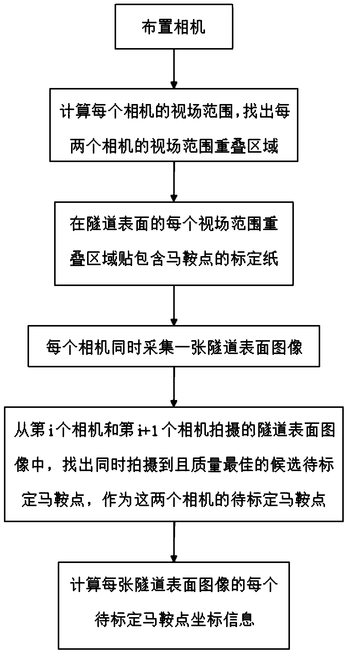
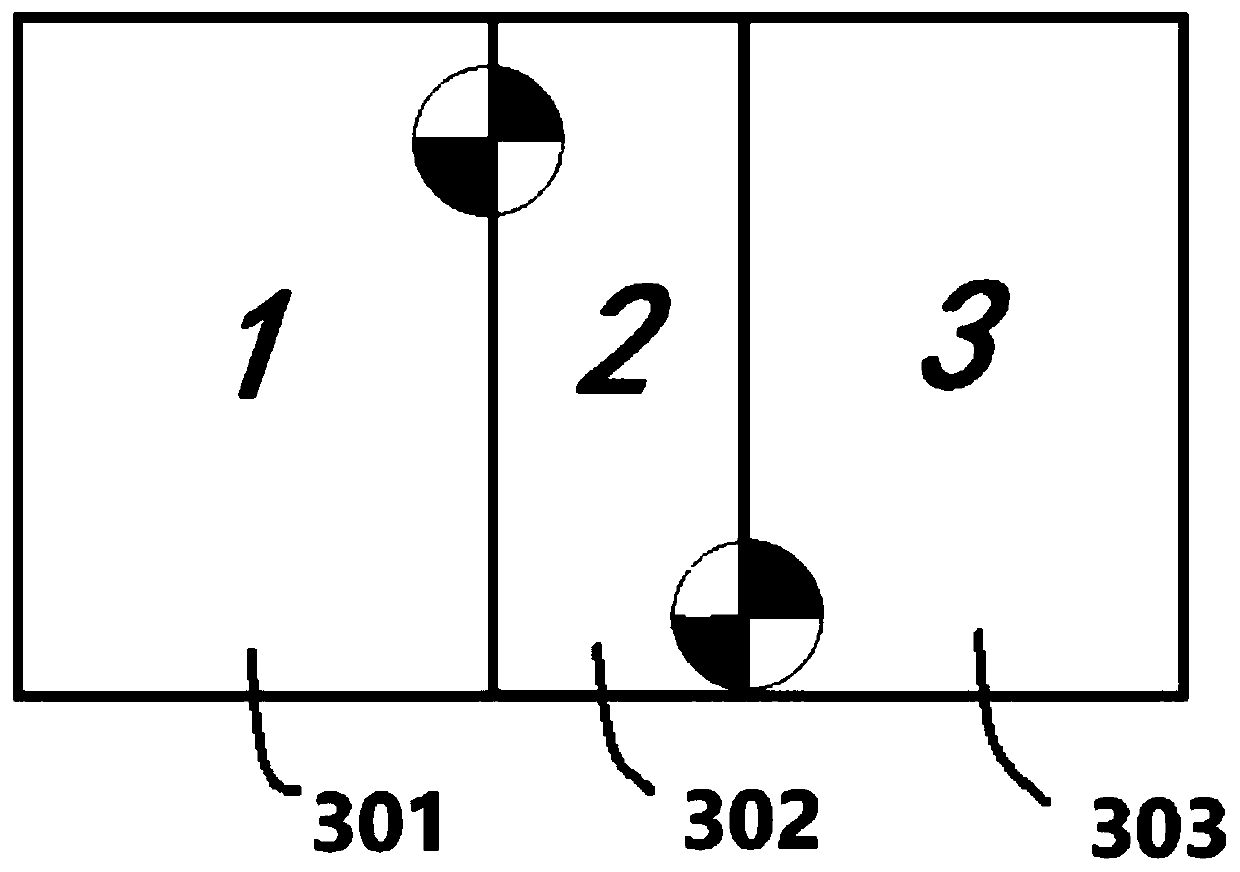
The invention discloses a shield tunnel surface image calibration method, a splicing method and a splicing system, and belongs to the field of tunnel detection. The method is characterized in that itis guaranteed that the optical axis of each camera is perpendicular to the surface of a tunnel, and the field angle of each camera is at least equal to (alphs-sigma(n-1)) / n; the calibration paper is pasted in an overlapped area of each view field range on the surface of the tunnel, so that each overlapped area comprises a plurality of candidate saddle points to be calibrated; each camera collectsa tunnel surface image at the same time; the candidate to-be-calibrated saddle points which are shot at the same time and have the best quality are found out as the to-be-calibrated saddle points of the adjacent cameras; and the coordinate information of each to-be-calibrated saddle point of each tunnel surface image is calcluated. According to the present invention, the saddle point of the view field overlapping area is selected as the calibration point, only one high-quality image needs to be shot, the operation is easy, and the method is suitable for the tunnel environment. The curved planeof the tunnel is unfolded into a plane through the mapping relation between the distorted image and the plane image, the splicing under the same coordinate system is achieved, the cost is lower, thetime is short, and the visual effect is better met.

Description

technical field [0001] The invention belongs to the field of tunnel detection, and more specifically relates to a shield tunnel surface image calibration method, splicing method and splicing system. Background technique [0002] When detecting tunnel cracks, due to the need to know the location, length and width of the cracks, and considering the visibility of the overall tunnel profile, it is necessary to make a puzzle to obtain a panoramic image. [0003] Among the images to be spliced, one image is used as a reference image, and the other images are called target images. Image registration requires spatial geometric transformation of the target image to align it with the reference image. Existing image stitching algorithms can be divided into region-based and feature-based algorithms. The mosaic method based on the regional gray intensity is to find the template with the highest similarity with the reference image in the mosaic image through the template, so as to find ...

Claims


Application Information

Patent Timeline
Patent Type & Authority Applications(China)
IPC IPC(8): G06T3/00G06T3/40G06T7/70
CPCG06T3/4038G06T7/70G06T3/14
Inventor 夏珉刘念
Owner HUAZHONG UNIV OF SCI & TECH
Learn More