
Rapid control prototyping system for researching electric device control algorithm

An electrical device and fast control technology, which is applied in general control systems, control/regulation systems, instruments, etc., can solve the problem of poor CPU operation speed, control signal output capability and feedback signal input capability, and is not suitable for small and medium-sized electrical devices. To meet the control needs and other issues, to achieve the effect of low cost, moderate price and high security

Pending Publication Date: 2019-07-19
顾云杰
View PDF0 Cites 0 Cited by
  • Summary
  • Abstract
  • Description
  • Claims
  • Application Information

AI Technical Summary

Problems solved by technology

The design of real-time target machine is the key to rapid control prototyping technology. Among the existing real-time target machines on the market, low-end models such as Raspberry Pi, STM32F4-Discovery, Arduino and other classic development boards can be used as simple real-time target machines. Inexpensive and flexible to use, but the CPU calculation rate, control signal output capability and feedback signal input capability are poor, and cannot meet the control requirements of high-speed and complex electrical devices such as power electronics; high-end models such as dSPACE, OPAL-RT, Speedgoat and other companies develop Performance real-time target machine, which uses the architecture combining Intel multi-core processor and FPGA, has powerful computing power and output capacity, and is suitable for the research and development of complex and large-scale systems, but its closed internal system, huge size and high price make it unsuitable for Research and development of small and medium electrical devices

Method used


Image

  • Rapid control prototyping system for researching electric device control algorithm
  • Rapid control prototyping system for researching electric device control algorithm
  • Rapid control prototyping system for researching electric device control algorithm

Examples


Embodiment Construction

[0020] In order to describe the present invention more specifically, the technical solutions of the present invention will be described in detail below in conjunction with the accompanying drawings and specific embodiments.

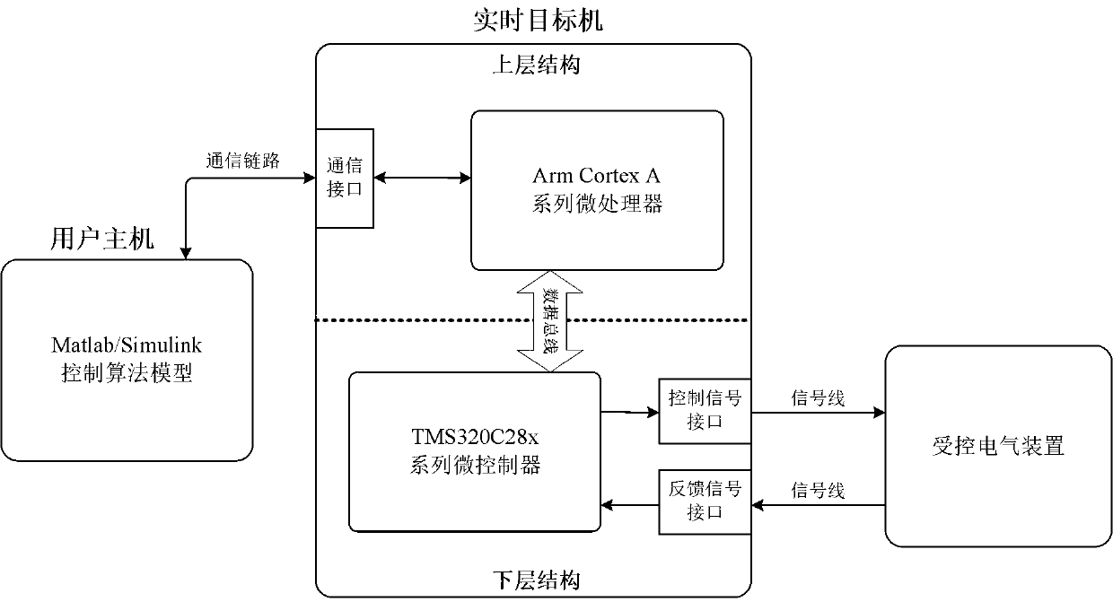
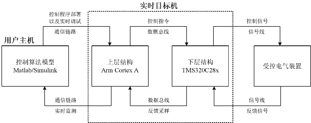
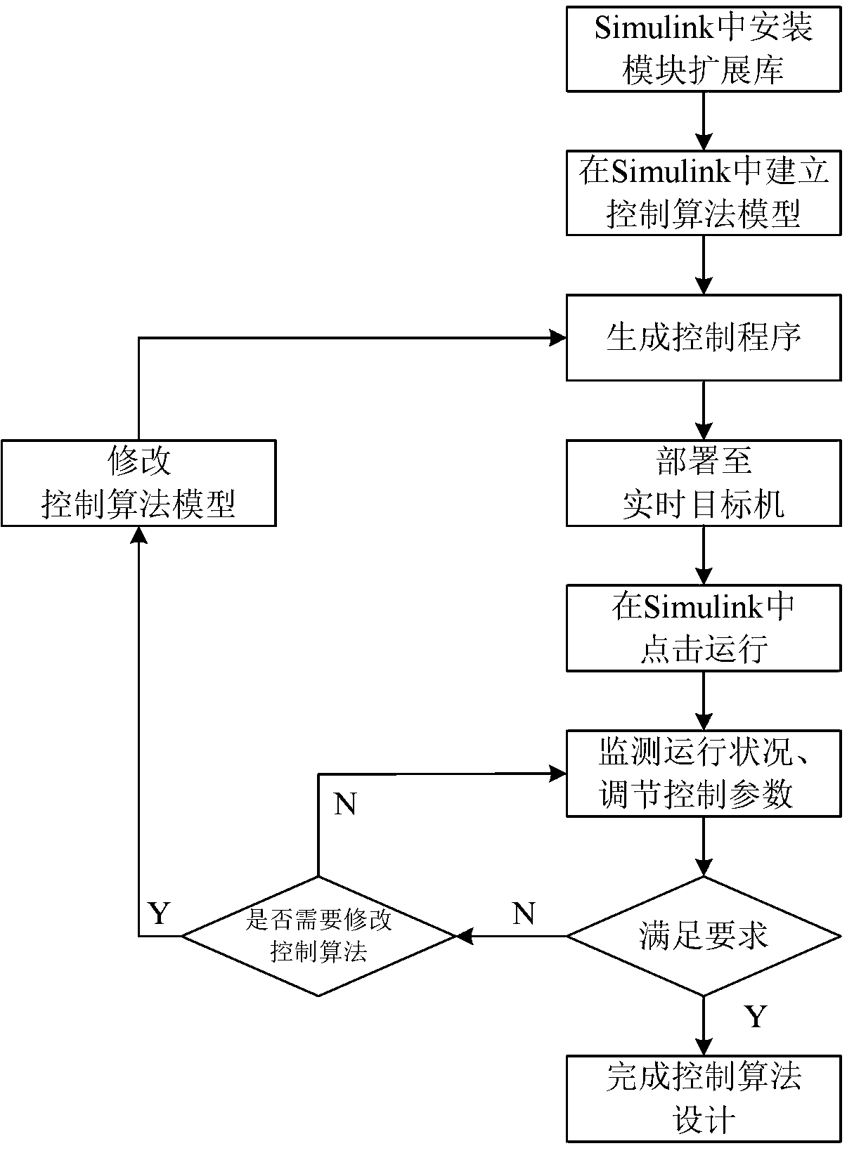
[0021] Such as figure 1 As shown, the present invention includes a user host computer and a real-time target computer. The user host is a personal computer, a workstation or a server equipped with Matlab / Simulink simulation software, which communicates with a real-time target machine through a communication link. The communication link can be realized by twisted pair, coaxial cable, optical fiber, radio and other communication media, and the communication protocol can be RS232, RS485, USB or IEEE 802 series protocol and other communication protocols. When using wireless communication, it can also realize the physical isolation between the user and the real-time target machine, thus effectively protecting the personal safety of the research and developmen...


PUM


Abstract

The invention discloses a rapid control prototyping system for researching an electric device control algorithm. The system comprises a user host and a real-time target machine. The user host is a personal computer, a workstation or a server in which Matlab / Simulink is installed. The real-time target machine comprises an upper layer structure and a lower layer structure. The upper layer structureis based on an Arm Cortex A series processor and is used for performing a control operation function and interacting with the user host. The lower layer structure is based on a TMS320C28x series microcontroller, is equipped with a control signal interface and a feedback signal interface and is used for interacting with a controlled electric device. The system is low in cost, high in operation capability and high in flexibility. After the user host establishes a control algorithm model, a researcher can rapidly deploy the algorithm to the real-time target machine for performance, and finally, real-time monitoring debugging is carried out on the controlled electric device through utilization of the control signal interface and the feedback signal interface, so researching speed is accelerated.

Description

technical field [0001] The invention belongs to the field of rapid control prototyping and specifically designs a rapid control prototyping system for the research and development of control algorithms of electrical devices. Background technique [0002] Today, the control of small and medium-sized electrical devices is mainly realized by embedded microcontrollers, that is, single-chip microcomputers. During the research and development process, after engineers model and simulate the control algorithm of the hardware system, they need to manually convert it into embedded program code and burn it into the chip for hardware verification, which brings a series of difficulties: when the control algorithm is relatively When it is complicated, the process of writing code will be more complicated, and it is difficult to check when an error occurs; during the debugging process, every time a variable is modified, the MCU program needs to be reprogrammed, which is time-consuming; obs...

Claims


Application Information

Patent Timeline
Patent Type & Authority Applications(China)
IPC IPC(8): G05B17/02
CPCG05B17/02
Inventor 顾云杰朱越向鑫蓝凌鑫
Owner 顾云杰
Learn More