
Dewatering machine

A dehydrator and outer cover technology, which is used in building fastening devices, removal of liquid/gas/vapor by centrifugal force, construction, etc., and can solve problems such as safety risks, poor closure and locking of dehydrator lids, etc.

Pending Publication Date: 2019-07-19
罗红荣
View PDF0 Cites 1 Cited by
  • Summary
  • Abstract
  • Description
  • Claims
  • Application Information

AI Technical Summary

Problems solved by technology

[0005] The object of the present invention is to provide a dehydrator to solve the safety risks that may be caused by the poor cover and locking of the existing dehydrator in view of the above-mentioned deficiencies in the prior art

Method used


Image

  • Dewatering machine
  • Dewatering machine
  • Dewatering machine

Examples


Embodiment Construction

[0027] In order to make the purpose, technical solutions and advantages of the embodiments of the present invention clearer, the technical solutions in the embodiments of the present invention will be clearly and completely described below in conjunction with the drawings in the embodiments of the present invention. Obviously, the described embodiments It is a part of embodiments of the present invention, but not all embodiments. The components of the embodiments of the invention generally described and illustrated in the figures herein may be arranged and designed in a variety of different configurations.

[0028] Accordingly, the following detailed description of the embodiments of the invention provided in the accompanying drawings is not intended to limit the scope of the claimed invention, but merely represents selected embodiments of the invention. It should be noted that, in the case of no conflict, various features in the embodiments of the present invention can be com...


PUM


Abstract

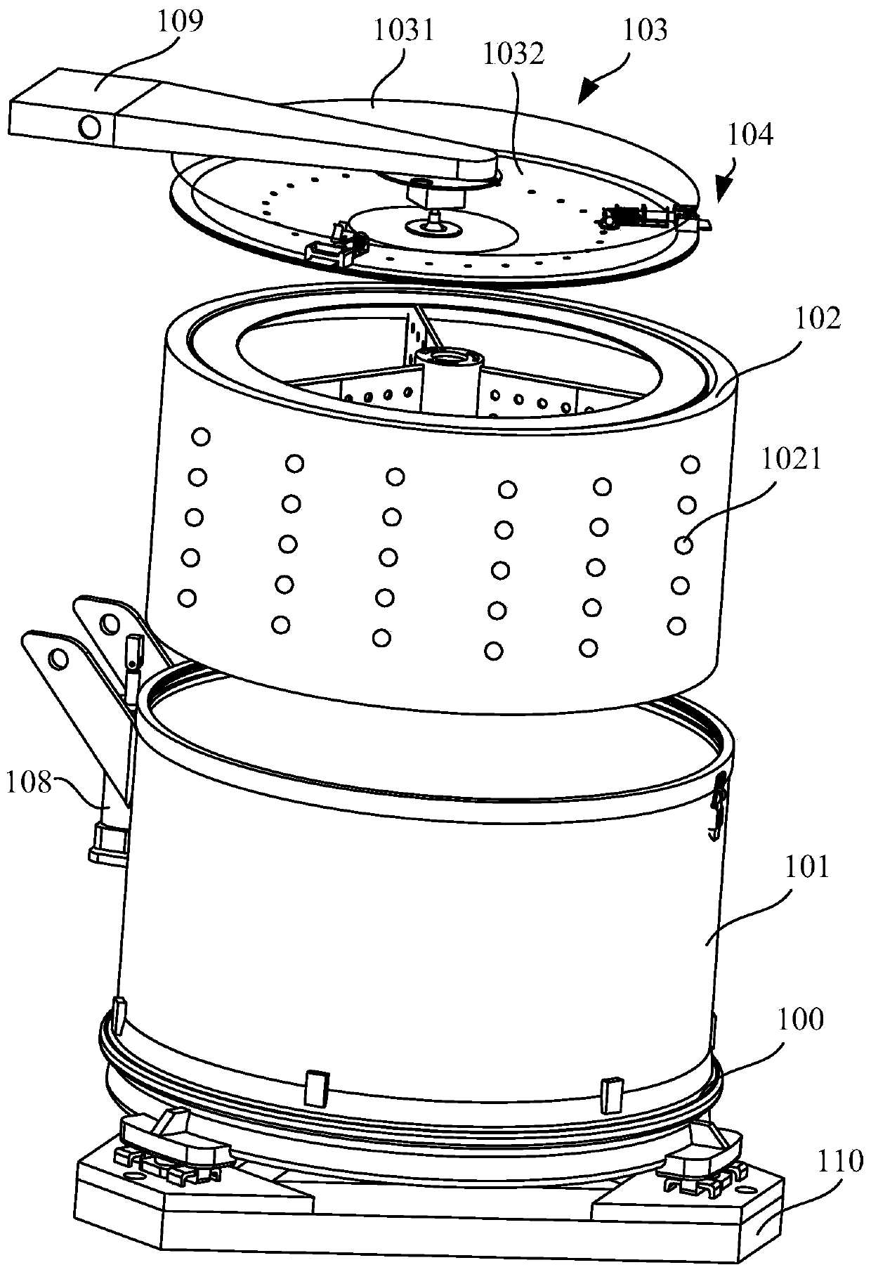
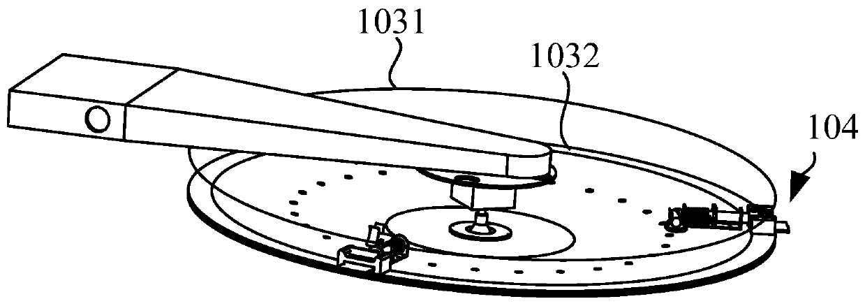
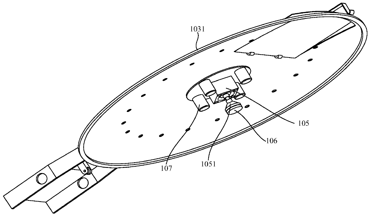
The invention provides a dewatering machine, and relates to the technical field of dewatering equipment. An outer cylinder is fixedly arranged on a base, an inner cylinder is arranged in the outer cylinder, and the base is provided with a driving device for driving the inner cylinder to rotate coaxially relative to the outer cylinder. The side wall of the inner cylinder is provided with drainage holes. The outer cylinder and the inner cylinder are provided with openings in the direction away from the base, and clothes or objects to be dewatered can be put into the inner cylinder or taken out of the inner cylinder through the openings. A cover body covers the opening of the inner cylinder, after covering, the cover body is locked with the inner cylinder through a locking device, it is ensured that the clothes or objects to be dewatered placed in the inner cylinder cannot be flung out of the cylinder body, and meanwhile the use safety of the dewatering machine is improved. The cover bodyis provided with a first detector, the first detector is used for detecting the locking state, including the locked or unlocked state, of the locking device and the inner cylinder, the locking stateof the locking device is fed back to an operator in real time accordingly, the occurrence of missing locking, forgotten locking or poor locking is prevented, and therefore the use safety of the dewatering machine is further improved.

Description

technical field [0001] The invention relates to the technical field of dehydration equipment, in particular to a dehydration machine. Background technique [0002] With the rapid development of my country's economy, people's living standards are getting higher and higher. People pay more attention to their own clothing after meeting the basic needs of life. Therefore, the demand for clothes is increasing. In order to meet this demand, the production of clothes has to be The process is optimized. In the production process of clothes, dehydration is a relatively important step. After the clothes are dyed, they need to be washed with water to remove floating colors, and then dehydrated. [0003] In the existing dehydration machines, a snap ring is usually provided on the edge of the dehydration bucket, and a handle is provided on the surface of the inner cover, and the turning handle is snapped into the snap ring to realize mutual locking. [0004] In the process of realizing ...

Claims


Application Information

Patent Timeline
IPC IPC(8): D06B15/10D06B23/18E05C1/10
CPCD06B15/10D06B23/18E05C1/10
Inventor 罗红荣詹涛陈卫华
Owner 罗红荣
Learn More