


Quick Research
Generate reliable direction feasibility study reports for your R&D in just a few steps.

Technical Q&A
Discover and master advanced knowledge NOW. Basics, ideas, possibilities, all at once.

Find Solutions
As an expert in R&D theories, this can generate solutions to your technical problems instantly.

Evaluate Feasibility
Analyze your overall solution with one click, know your potential R&D risks in advance.

Monitor Landscape
Get weekly tech updates, stay abreast of the latest tech innovations and key insights.
Pedal feel simulator for vehicle and vehicle having same
A simulator and pedal technology, applied in the field of vehicles, can solve the problems of driver inconvenience, slow response speed of the braking system, poor braking performance, etc., and achieve the effect of fast braking response, easy design requirements, and reasonable braking force
- Summary
- Abstract
- Description
- Claims
- Application Information
AI Technical Summary
Problems solved by technology
Method used
Image

Examples
Embodiment 1
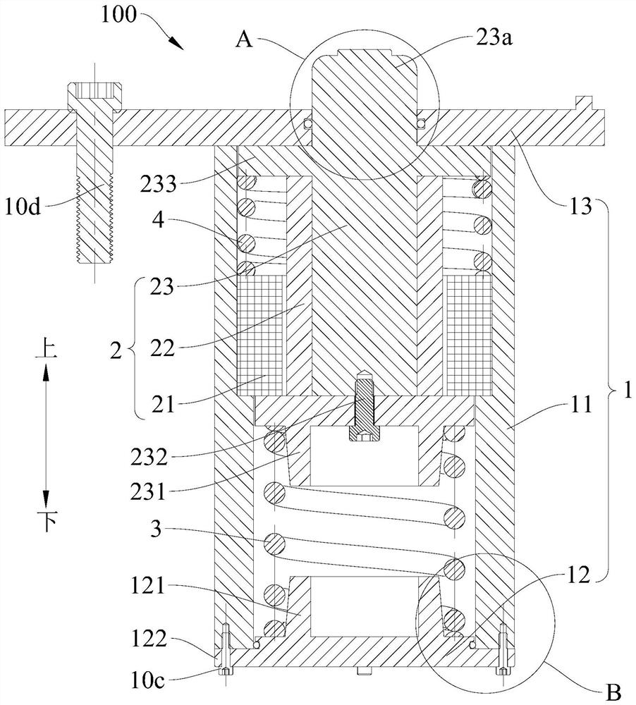
[0067] In this example, if Figure 1-Figure 7As shown, the pedal feel simulator 100 includes a housing 1 , a linear motor 2 , a first elastic member 3 and a second elastic member 4 .
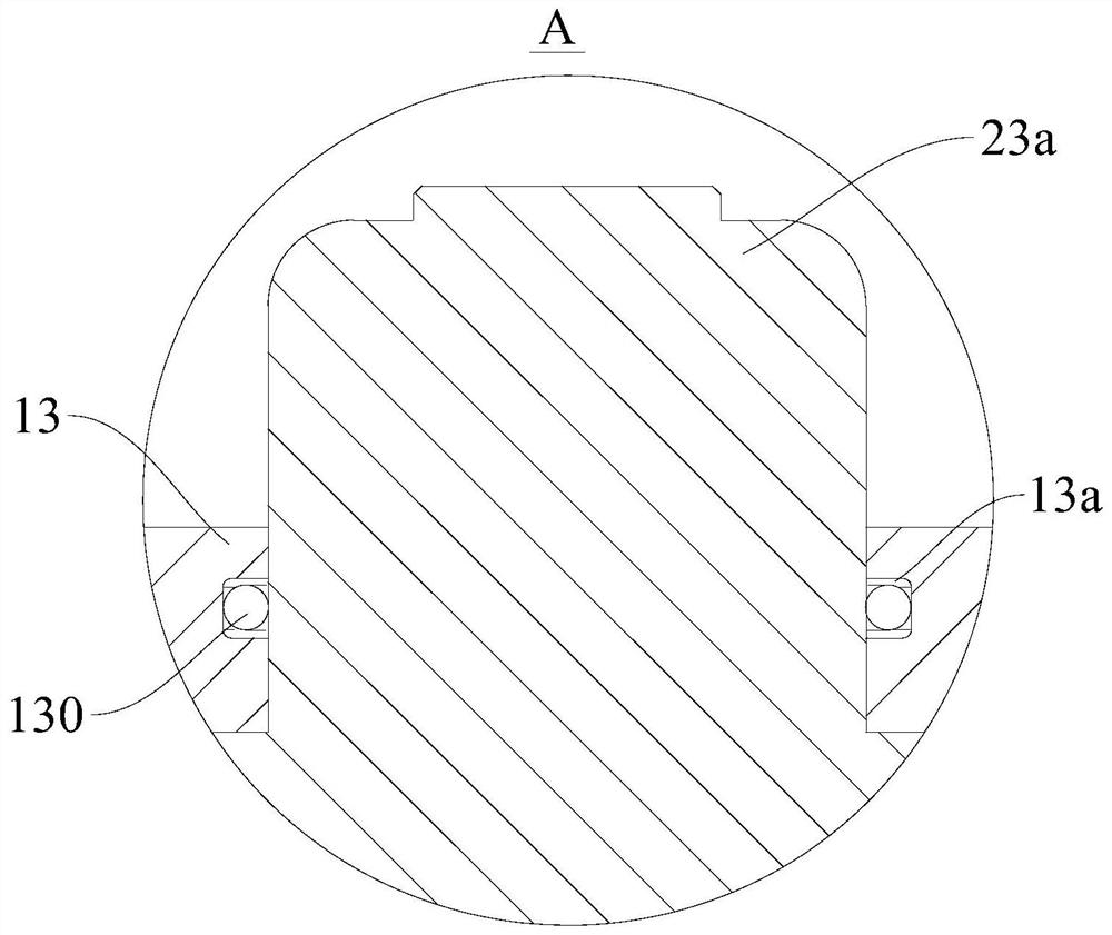
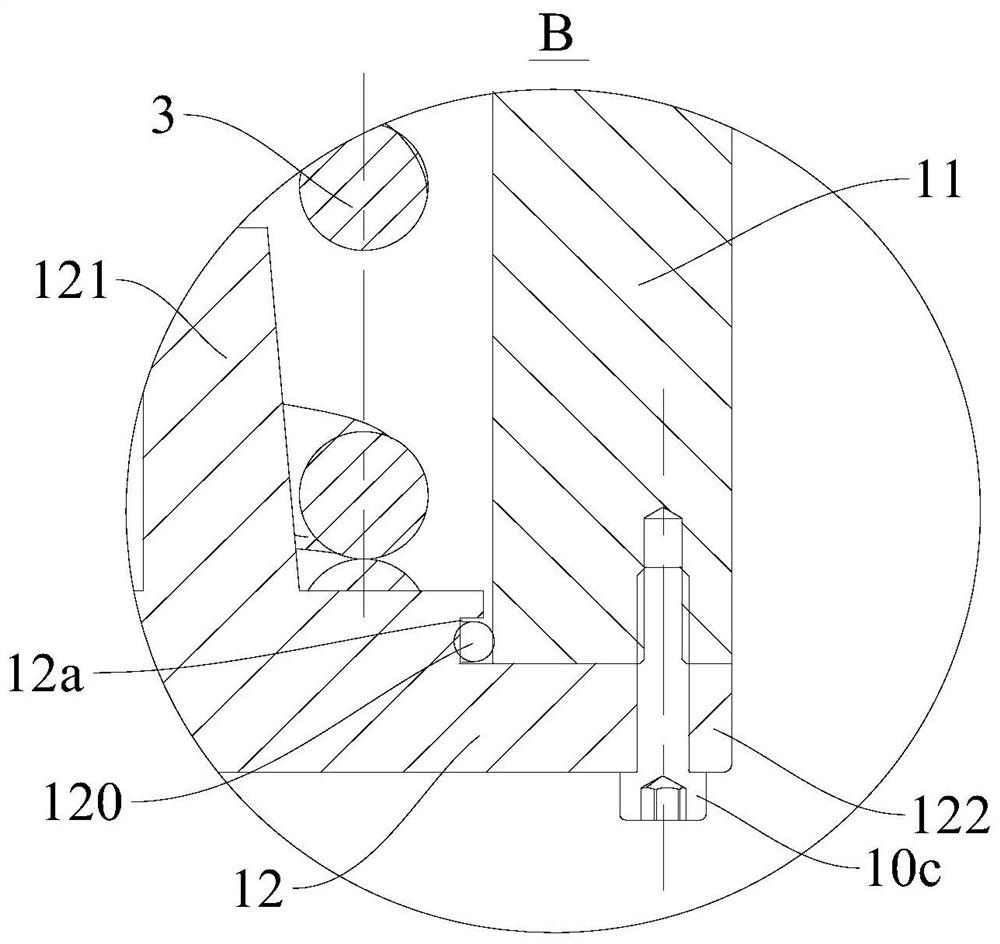
[0068] The housing 1 includes a main cylinder block 11 , a bottom cover 12 and a fixing plate 13 . The main cylinder block 11 is roughly formed into a cylindrical structure. Both ends of the main cylinder block 11 in the axial direction are open. one end (for example, as figure 1 The lower end in the middle), the fixing plate 13 is provided at the other axial end of the master cylinder 11 (for example, as figure 1 The upper end of the middle), so that the bottom cover 12, the main cylinder 11 and the fixing plate 13 together define a closed accommodating space. Specifically, as Figure 1-Figure 6 As shown, the upper end of the master cylinder block 11 is formed with a first connecting portion 111, the first connecting portion 111 is formed to protrude outward along the radial direction of the...
Embodiment 2
[0077] like Figure 8 As shown, the structure of this embodiment is substantially the same as that of the first embodiment, and the same components are given the same reference numerals, the difference is that: when the driver does not step on the pedal 101 and the pedal feel simulator 100 is in the initial position, the first Both the elastic member 3 and the second elastic member 4 are in a natural state, the two ends of the first elastic member 3 are respectively abutted against the inner wall of the housing 1 and the second end 23b of the motor push rod 23, and the lower end of the second elastic member 4 The inner wall of the housing 1 abuts against each other, and the upper end of the second elastic member 4 is spaced apart from the second end 23 b of the motor push rod 23 . When the driver steps on the pedal 101, the first elastic member 3 first works to apply an elastic force to the motor push rod 23. When the displacement of the pedal 101 reaches its set value, or the...
PUM
 Abstract
Description
Claims
Application Information
 - R&D Engineer
- R&D Manager
- IP Professional
- Industry Leading Data Capabilities
- Powerful AI technology
- Patent DNA Extraction
Browse by: Latest US Patents, China's latest patents, Technical Efficacy Thesaurus, Application Domain, Technology Topic, Popular Technical Reports.
© 2024 PatSnap. All rights reserved.Legal|Privacy policy|Modern Slavery Act Transparency Statement|Sitemap|About US| Contact US: help@patsnap.com