
High-speed cold rolled steel strip uncoiling automatic guiding and feeding device

A cold-rolled steel strip, high-speed technology, applied in the direction of metal rolling, metal rolling, manufacturing tools, etc., can solve the problems of reducing feeding efficiency, offset jamming, etc., and achieve the effect of increasing the feeding rate

Active Publication Date: 2019-07-19
广东宝盛兴实业有限公司
View PDF11 Cites 10 Cited by
  • Summary
  • Abstract
  • Description
  • Claims
  • Application Information

AI Technical Summary

Problems solved by technology

[0004] However, in actual use, there are still many disadvantages. For example, when feeding the steel strip, it is easy to shift and jam the material, thereby reducing the feeding efficiency.

Method used

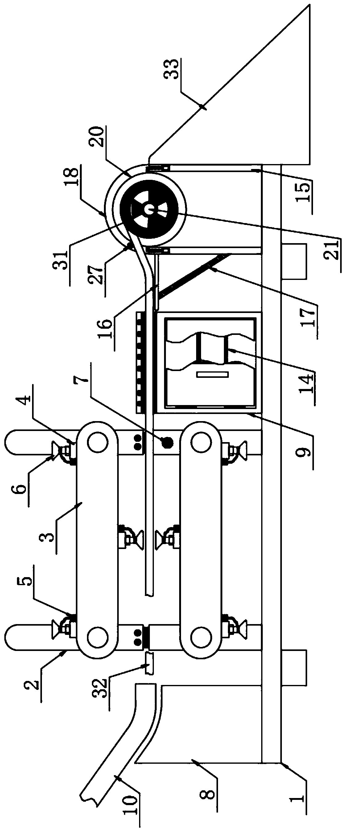
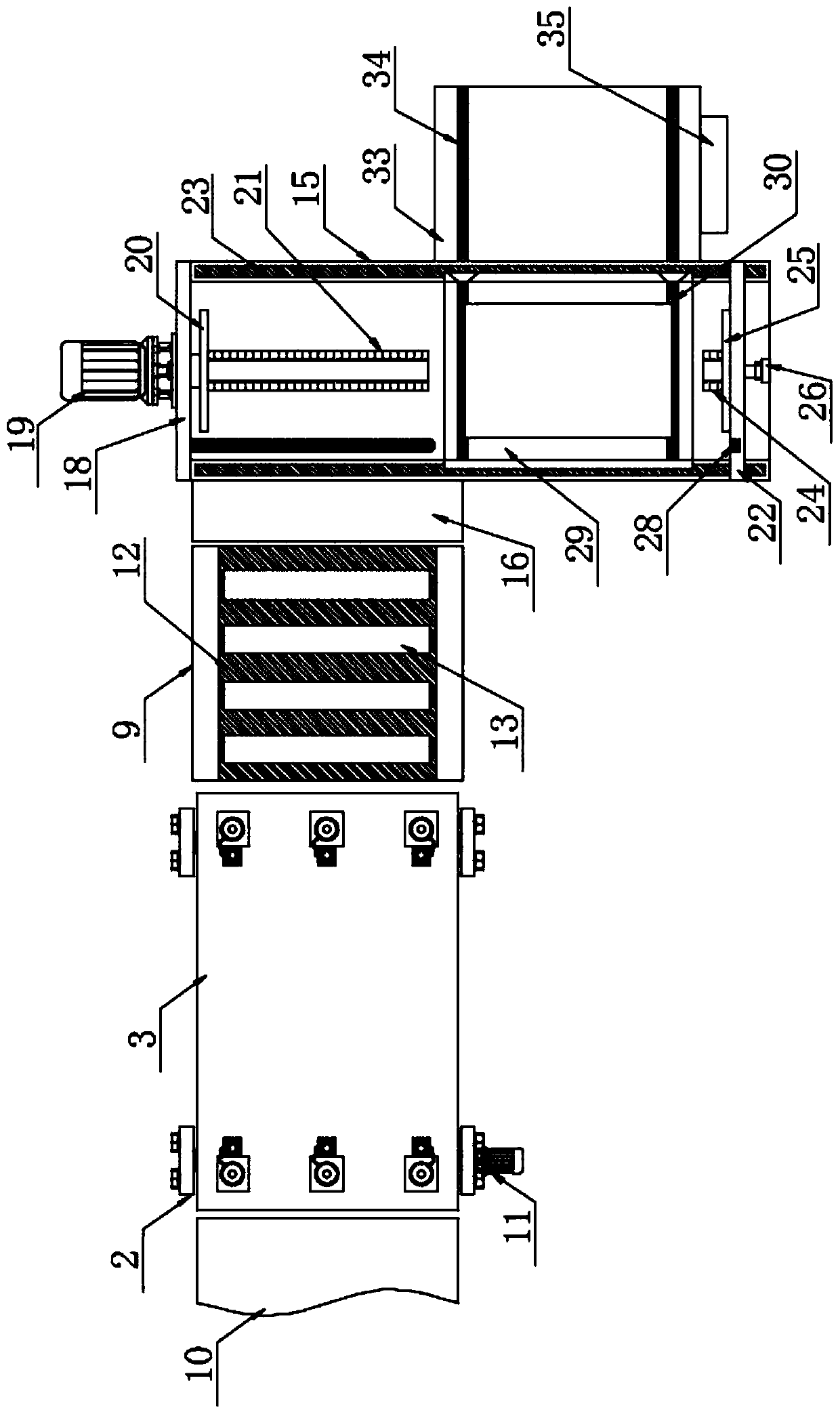

Image

  • High-speed cold rolled steel strip uncoiling automatic guiding and feeding device
  • High-speed cold rolled steel strip uncoiling automatic guiding and feeding device
  • High-speed cold rolled steel strip uncoiling automatic guiding and feeding device

Examples


Embodiment 1

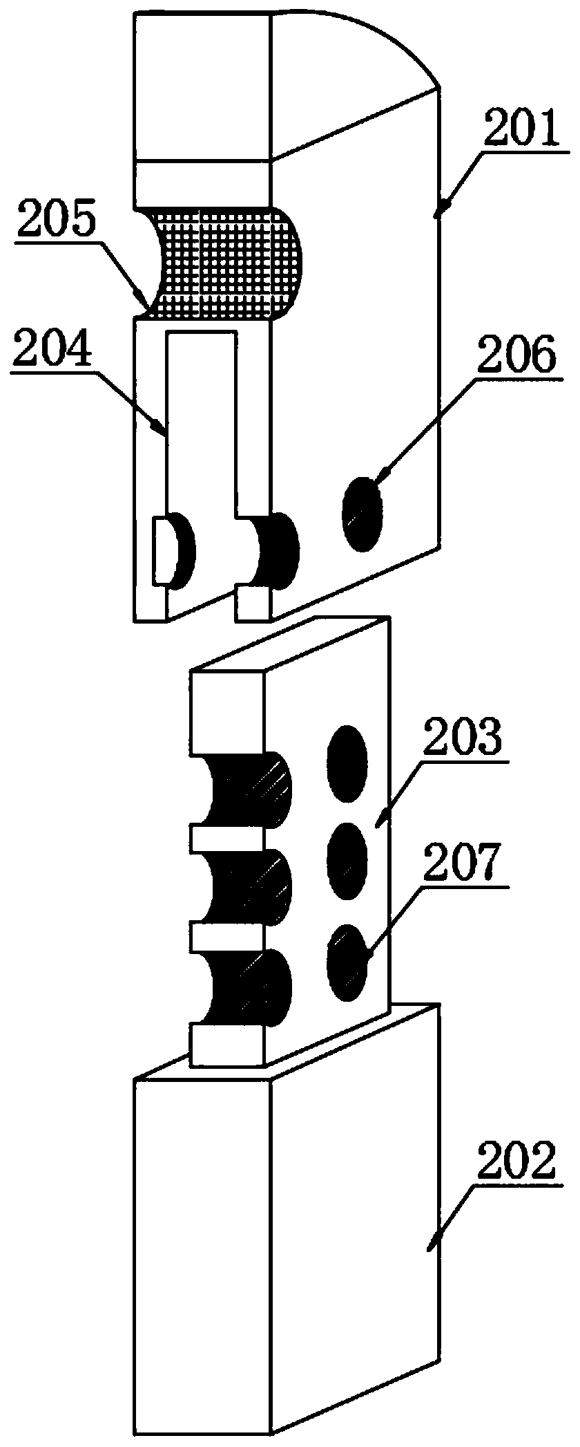
[0030] The present invention provides such Figure 1-5 and Figure 8 A high-speed cold-rolled steel strip uncoiling automatic lead-in feeding device shown includes a base 1, adjusting plates 2 are arranged on both sides of the top of the base 1, and a conveyor belt 3 is arranged between two sets of adjusting plates 2 , the surface of the conveyor belt 3 is fixed with a first electric push rod 4, the end of the first electric push rod 4 is fixedly connected with a vacuum suction cup 6, and one side of the first electric push rod 4 is fixed with a vacuum pump 5, The vacuum chuck 6 is connected to the vacuum pump 5 through a connecting pipe, and an infrared detector 7 is fixed inside a group of the adjustment plates 2, wherein the infrared detector 7 is a DT-7380 infrared detector. It is beneficial to detect the real-time position of the vacuum chuck 6, and transmit the electric signal to the PLC controller 35, and then the PLC controller 35 controls the working conditions of th...

Embodiment 2

[0042] The difference from Example 1 is that referring to the description Figure 6-7 , the bottom of the first limiting groove 30 is provided with a fitting groove 38, and a plurality of springs 41 are evenly distributed inside the fitting groove 38, which is beneficial to move the reel 31 wound with the steel strip 32 from the inclined platform 33 When rolling into the material holder 29, an upward elastic force is provided to the reel 31 by the spring 41, to slow down the pressure on the material holder 29 when the reel 31 falls, to prolong the service life of the material holder 29, the bottom of the material holder 29 A plurality of vertical rods 43 are evenly distributed, and the vertical rods 43 are fixedly connected with the bottom of the material holder 29, and the bottom ends of the vertical rods 43 are fixedly connected with rollers 42, which can greatly reduce the impact on the material holder 29 when it moves along the material rack 15. At the same time, the frict...


PUM


Abstract

The invention discloses a high-speed cold rolled steel strip uncoiling automatic guiding and feeding device, and particularly relates to the technical field of cold rolling equipment. The high-speed cold rolled steel strip uncoiling automatic guiding and feeding device comprises a base, the two sides of the top of the base are provided with adjusting plates, a conveying belt is arranged between the two adjusting plates, first electric push rods are fixedly arranged on the surface of the conveying belt, the end portions of the first electric push rods are fixedly connected with vacuum chucks, one sides of the first electric push rods are fixedly provided with vacuumizing pumps, the vacuum chucks and the vacuumizing pumps communicate with each other through connecting pipes, and an infrareddetector is fixedly arranged on the inner side of one of adjusting plates. According to the high-speed cold rolled steel strip uncoiling automatic guiding and feeding device, the first electric push rods connected with the vacuum chucks are arranged on the surface of the conveying belt, and the position change of the first electric push rods is monitored in real time through the infrared detector,so that the working states of the vacuumizing pumps on one sides of the two adjacent first electric push rods are controlled so as to ensure stable conveying of a steel strip.

Description

technical field [0001] The invention relates to the technical field of cold rolling equipment, and more specifically, the invention relates to an automatic lead-in feeding device for uncoiling a high-speed cold-rolled steel strip. Background technique [0002] The cold-rolled steel strip has shown great competitiveness in the market due to its superior performance and competitive cost. The raw material of the cold-rolled steel strip is a coiled steel strip. During rolling, the steel strip needs to be rolled After pulling to a certain extent, it can enter the subsequent equipment for further processing. [0003] The invention patent of patent application publication number CN 105382034 A discloses a high-speed cold-rolled steel bar uncoiling automatic lead-in feeding device, the device includes a feeding frame, a lifting mechanism is arranged on one side of the feeding frame, and a clamp is connected to the lifting mechanism. A guide plate is set above the feeding frame, a w...

Claims


Application Information

Patent Timeline
Patent Type & Authority Applications(China)
IPC IPC(8): B21B15/00B21C47/18B21C47/34B21C51/00
CPCB21B15/00B21B2015/0064B21C47/18B21C47/34B21C51/00
Inventor 陈锐陈郁佳
Owner 广东宝盛兴实业有限公司
Learn More