Daylighting system
A lighting system and weather technology, applied in the field of lighting systems, can solve problems such as false work, and achieve the effect of suppressing false work
- Summary
- Abstract
- Description
- Claims
- Application Information
AI Technical Summary
Problems solved by technology
Method used
Image
Examples
Embodiment approach 1
[0052] [structure]
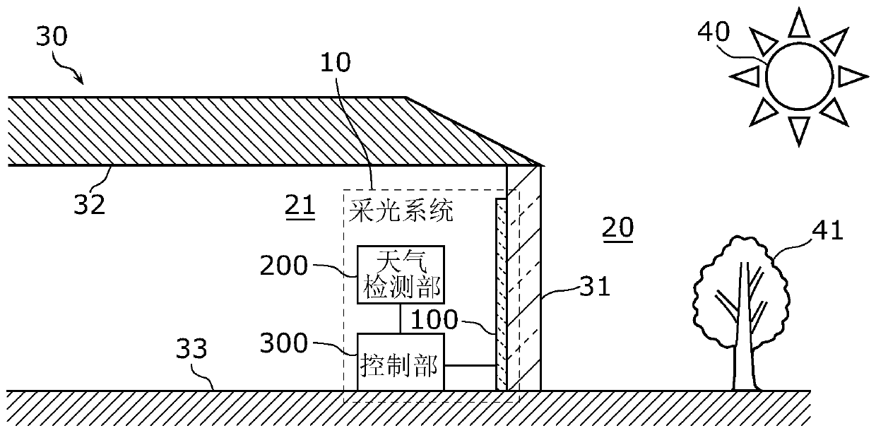
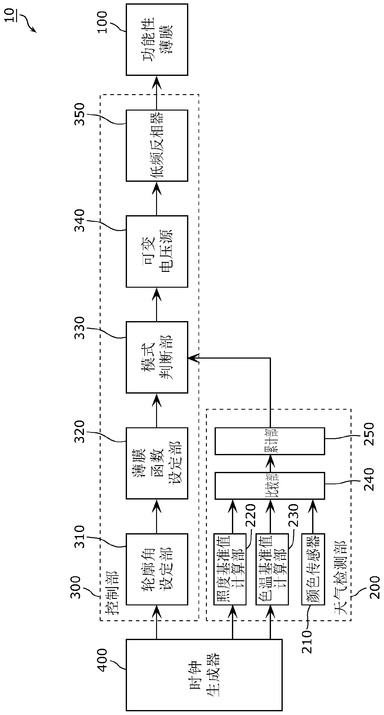
[0053] First, for an overview of the daylighting system according to Embodiment 1, use figure 1 as well as figure 2 Be explained. figure 1 It is a schematic diagram which shows the structure and application example of the daylighting system 10 which concerns on this embodiment. figure 2 It is a block diagram showing the functional configuration of the lighting system 10 according to this embodiment.
[0054] Such as figure 1 As shown, the daylighting system 10 is applied to a building 30 and is a system for introducing light from the exterior 20 of the building 30 into the interior 21 of the building 30 . The daylighting system 10 adjusts the amount of light introduced into the room 21 according to the weather.
[0055] Such as figure 1 as well as figure 2 As shown, the daylighting system 10 includes a functional film 100 , a weather detection unit 200 , and a control unit 300 . The functional film 100 is arranged on the window 31 of the buildin...
Embodiment approach 2
[0205] Next, Embodiment 2 will be described.
[0206] [Direct light and scattered light]
[0207] In this embodiment, the weather is detected using the ratio of direct light and scattered light. Below, first, for direct light and scattered light, use Figure 9A to Figure 9C Be explained.
[0208] Figure 9A to Figure 9C It shows that the weather at the installation location (building 30) of the functional film 100 according to this embodiment is sunny, the weather at the installation location (building 30) is cloudy, and the installation location (building 30) is in A schematic diagram of direct light 90 and scattered light 91 in the shade of a building 93 .
[0209] Direct light 90 is light directly incident on the functional film 100 from the sun 40 (photosphere of the sun). The amount of direct sunlight, which corresponds to the so-called irradiance of direct sunlight. The amount of direct sunlight is the irradiance received on a plane perpendicular to the incident di...
Embodiment approach 3
[0285] [summary]
[0286] As described in Embodiment 1, the control unit 300 can switch between the automatic mode of controlling the transmittance of the functional film 100 based on the detection result of the weather detection unit 200 and the manual mode of controlling the transmittance of the functional film 100 according to the user's operation. model.
[0287] For example, the user operates a user interface such as an operation panel that accepts user operations to switch between two control modes, an automatic mode and a manual mode. In general, in order to install the operation panel, a large-scale construction such as embedding the operation panel in a structure near a window is required.
[0288] Then, in Embodiment 3, the daylighting system in which the installation work of user interfaces such as an operation panel is reduced in scale will be described.
[0289] In addition, in the description of Embodiment 3 and the drawings used for the description, the X axis...
PUM
| Property | Measurement | Unit |
|---|---|---|
| thickness | aaaaa | aaaaa |
| refractive index | aaaaa | aaaaa |
| refractive index | aaaaa | aaaaa |
Abstract
Description
Claims
Application Information
 - R&D Engineer
- R&D Manager
- IP Professional
- Industry Leading Data Capabilities
- Powerful AI technology
- Patent DNA Extraction
Browse by: Latest US Patents, China's latest patents, Technical Efficacy Thesaurus, Application Domain, Technology Topic, Popular Technical Reports.
© 2024 PatSnap. All rights reserved.Legal|Privacy policy|Modern Slavery Act Transparency Statement|Sitemap|About US| Contact US: help@patsnap.com


