
DC output circuit and charging pile

A technology of DC output and charging pile, applied in the direction of DC network circuit device, parallel operation of DC power supply, circuit device, etc., can solve the problem that the residual voltage cannot be guaranteed to be absolutely equal, the switching device is damaged, etc., to prevent backflow and avoid current impact. Effect

Inactive Publication Date: 2019-07-16
XIAN TGOOD INTELLIGENT CHARGING TECH CO LTD
View PDF3 Cites 1 Cited by
  • Summary
  • Abstract
  • Description
  • Claims
  • Application Information

AI Technical Summary

Problems solved by technology

[0003] DC output series-parallel switching involves switching between two or more outputs. When the series circuit is disconnected, due to the existence of the output capacitor, the output voltage will not directly drop to zero, and the residual voltage cannot be guaranteed to be absolutely equal. At the moment of parallel connection, the residual voltage of the two DC output capacitors will flow back, and the current impact generated by the voltage difference will easily cause damage to the switching device.

Method used


Image

  • DC output circuit and charging pile
  • DC output circuit and charging pile
  • DC output circuit and charging pile

Examples


Embodiment Construction

[0041] In order to make the purposes, technical solutions and advantages of the embodiments of the present application clearer, the technical solutions in the embodiments of the present application will be clearly and completely described below in conjunction with the drawings in the embodiments of the present application. Obviously, the described embodiments It is a part of the embodiments of this application, not all of them. The components of the embodiments of the application generally described and illustrated in the figures herein may be arranged and designed in a variety of different configurations.

[0042] Accordingly, the following detailed description of the embodiments of the application provided in the accompanying drawings is not intended to limit the scope of the claimed application, but merely represents selected embodiments of the application. Based on the embodiments in this application, all other embodiments obtained by persons of ordinary skill in the art w...


PUM


Abstract

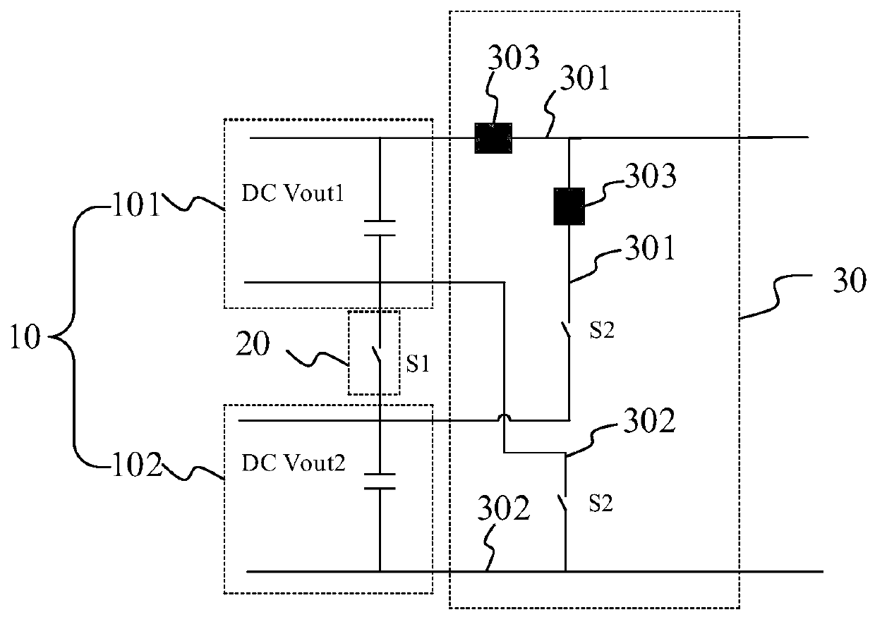
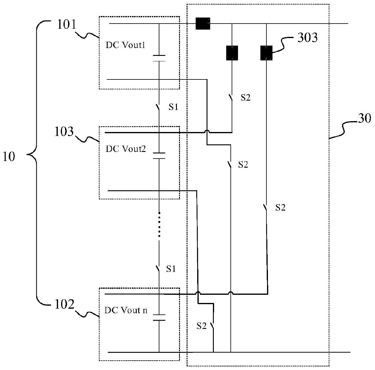
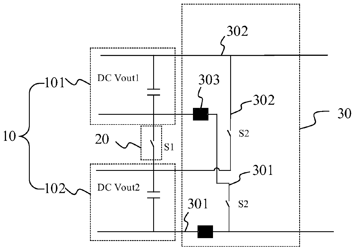
The invention proposes a DC output circuit and a charging pile. N DC output units are sequentially connected in series by a series assembly, first poles of the N DC output units are respectively connected to corresponding first branches, a backflow prevention device is correspondingly arranged on each first branch, and second poles of the N DC output units are respectively connected to corresponding second branches. A series state or a parallel state of each DC output unit is switched by the series assembly and a parallel assembly; and by arranging the backflow prevention device on each firstbranch adjacent to the first pole of each DC output unit, backflow of an output current of each DC output unit is prevented when parallel instantaneous moment is switched, and thus, the situation thatthe device is easily damaged by current impact generated by voltage different is prevented.

Description

technical field [0001] The present application relates to the charging field, in particular, to a DC output circuit and a charging pile. Background technique [0002] With the development of technology, the demand for DC output power is greater and greater. In order to be compatible with high voltage and low voltage and high current, DC output series-parallel switching circuits are widely used. [0003] DC output series-parallel switching involves switching between two or more outputs. When the series circuit is disconnected, the output voltage will not drop directly to zero due to the existence of the output capacitor, and the residual voltage cannot be guaranteed to be absolutely equal. At the moment of parallel connection, the residual voltage of the two DC output capacitors will flow back, and the current impact generated by the voltage difference will easily cause damage to the switching device. Contents of the invention [0004] The purpose of the present applicatio...

Claims


Application Information

Patent Timeline
IPC IPC(8): H02J1/00H02J1/10H02H9/04
CPCH02H9/04H02J1/00H02J1/10
Inventor 石浩郭进
Owner XIAN TGOOD INTELLIGENT CHARGING TECH CO LTD
Learn More