Multi-missile time cooperative guidance method with collision angle constraint

A technology of time coordination and collision angle, applied in guidance methods, complex mathematical operations, offensive equipment, etc., can solve problems such as non-coordination, and achieve the effect of ensuring real-time performance, easy solution, and simple dynamic equation form.

Active Publication Date: 2019-07-16
XI AN JIAOTONG UNIV
View PDF4 Cites 25 Cited by
  • Summary
  • Abstract
  • Description
  • Claims
  • Application Information

AI Technical Summary

Problems solved by technology

However, the first collaborative strategy in the prior art mainly studies the guidance law with controllable collision time for a single target, and then sets the same flight time for each missile to hit the target at the same time. There is no communication between the missiles. Coordination in the true sense; while the second guidance strategy in the prior art is mainly based on the multi-agent coordination theory to design the guidance law. Although the mutual communication between the missiles has been realized in this way, it is assumed that the acceleration of the missile speed and direction is controllable. Missiles with solid rocket motors are not suitable
In addition, there are few studies in the prior art that consider both the end collision angle constraint and the multi-missile time coordination

Method used


Image

  • Multi-missile time cooperative guidance method with collision angle constraint
  • Multi-missile time cooperative guidance method with collision angle constraint
  • Multi-missile time cooperative guidance method with collision angle constraint

Examples


Embodiment Construction

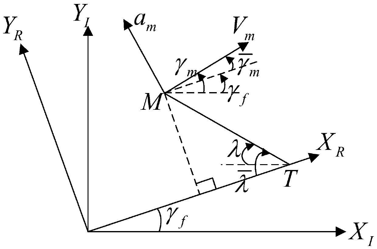
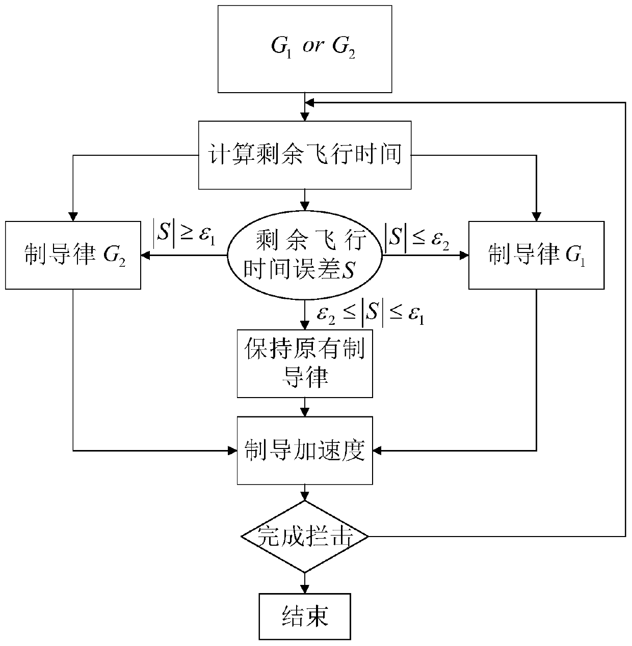
[0067] The present invention is a multi-missile time cooperative guidance method with collision angle constraints. In order to meet the requirements of the missile terminal collision angle constraints, the inertial coordinate system where the missile and the target are located is rotated by the expected collision angle γ f Obtain the reference coordinate system, establish a new missile motion equation in the reference coordinate system, and design the guidance law constrained by the terminal collision angle based on the optimal control theory; The remaining flight time error is used as the sliding mode surface, so that the remaining flight time of the missile tends to the expected remaining flight time, and the time-controllable guidance law is designed based on the sliding mode control theory; in order to meet the requirements of the missile terminal collision angle and time constraints, the design The switching strategy enables the missile to hit the target at the desired tim...


PUM


Abstract

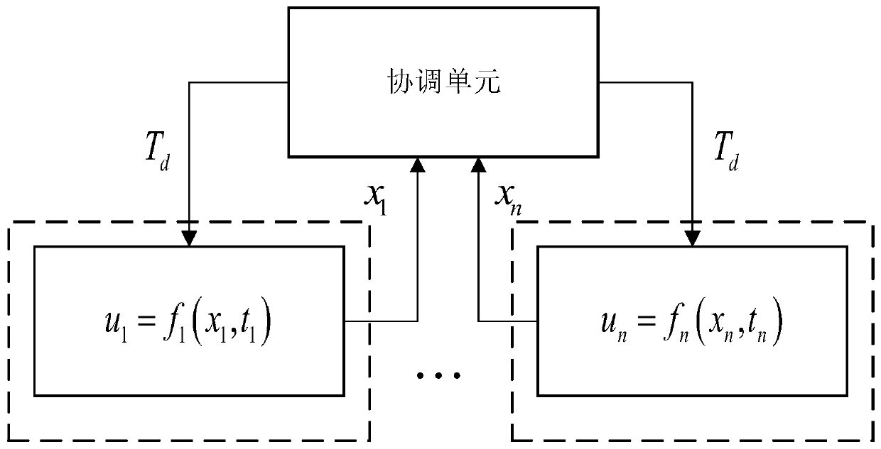
The invention discloses a multi-missile time cooperative guidance method with collision angle constraint. A new missile and target dynamic equation is built under the reference coordinate system, andon the basis of the optimal control theory, a guidance rule of the tail end collision angle constraint is designed; the error between current remaining flying time of missiles and the expected remaining flying time serves as a sliding mode surface, the remaining flying time of the missiles has tendency to the expected remaining flying time, on the basis of the sliding mode control theory, the timecontrollable guidance rule is designed; the switching strategy of the tail end collision angle controllable guidance rule and the time controllable guidance rule is designed for enabling the missilesto hit the target at the expected time and angle; a multi-missile time cooperative communication network is built, on the basis of a dual-layer cooperative guidance framework, coordinated variable isdesigned to enable the remaining flying time of the missiles to tend to be consistent, the missiles can hit the target at the same time at the expected collision angles, and multi-missile time cooperation in real meaning is achieved.

Description

technical field [0001] The invention belongs to the technical field of missile guidance, and in particular relates to a multi-missile time cooperative guidance method with collision angle constraints. Background technique [0002] With the continuous development of anti-missile technology in various countries, a single missile can no longer complete the combat tasks of penetration and interception. The coordinated guidance law strategy in which multiple missiles carry out saturation attacks on the same target at the same time can effectively improve the battlefield survivability and interception success rate of missiles. At present, most of the research on coordinated guidance at home and abroad focuses on time coordination, and time coordination guidance strategies can be divided into the following two types: [0003] 1) Set the expected flight time in advance, control the collision time of each missile independently, and launch all missiles at the same time, then each mis...

Claims


Application Information

Patent Timeline
IPC IPC(8): F41G3/00G06F17/50G06F17/11G06F17/15
CPCF41G3/00G06F17/11G06F17/15G06F2119/18G06F30/20
Inventor 蔡远利刘涛瑜
Owner XI AN JIAOTONG UNIV
Why Eureka
Try Eureka