Floor for lying of sow parturition fence
A technology for farrowing crates and floors, applied in the field of animal husbandry, can solve the problems of weak buffering force for sows, large hook bending, and high processing difficulty, and achieve the effects of convenient and fast processing, beautiful appearance and convenient installation.
- Summary
- Abstract
- Description
- Claims
- Application Information
AI Technical Summary
Problems solved by technology
Method used
Image
Examples
Embodiment 1
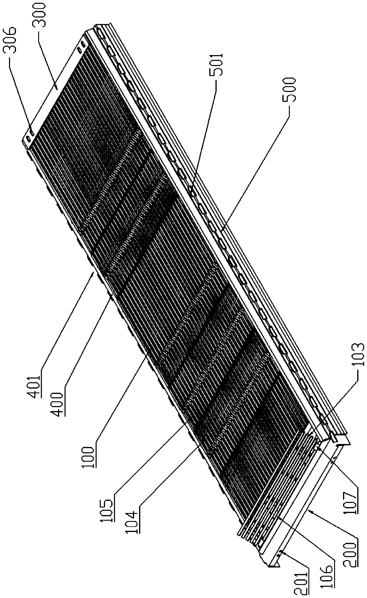
[0051] like figure 1 , 7 As shown, a floor for sows to lie on in a farrowing pen, including: a manure slat main body 100, a support frame and special-shaped support steel bars. in:
[0052] The main body 100 of the leaking manure board includes a first beam 101, several uniformly distributed longitudinal support bars 102 welded on the top of the first beam 101, a second beam 109 and a reversible rear cover 103; the longitudinal support bar 102 is a triangle with an inverted triangle cross section. Steel, the structure of an inverted triangle is narrow at the top and wide at the bottom, so it will not pinch the nipples and limbs of the sow. The position where the crossbeams 101 are connected is a raised structure 104, and between two adjacent first crossbeams 101 is a recessed structure 105. The first crossbeams 101 and the longitudinal support bars 102 form a manure leakage hole, and the first crossbeams 101 make the main body 100 of the manure leakage plate Stress is not e...
Embodiment 2
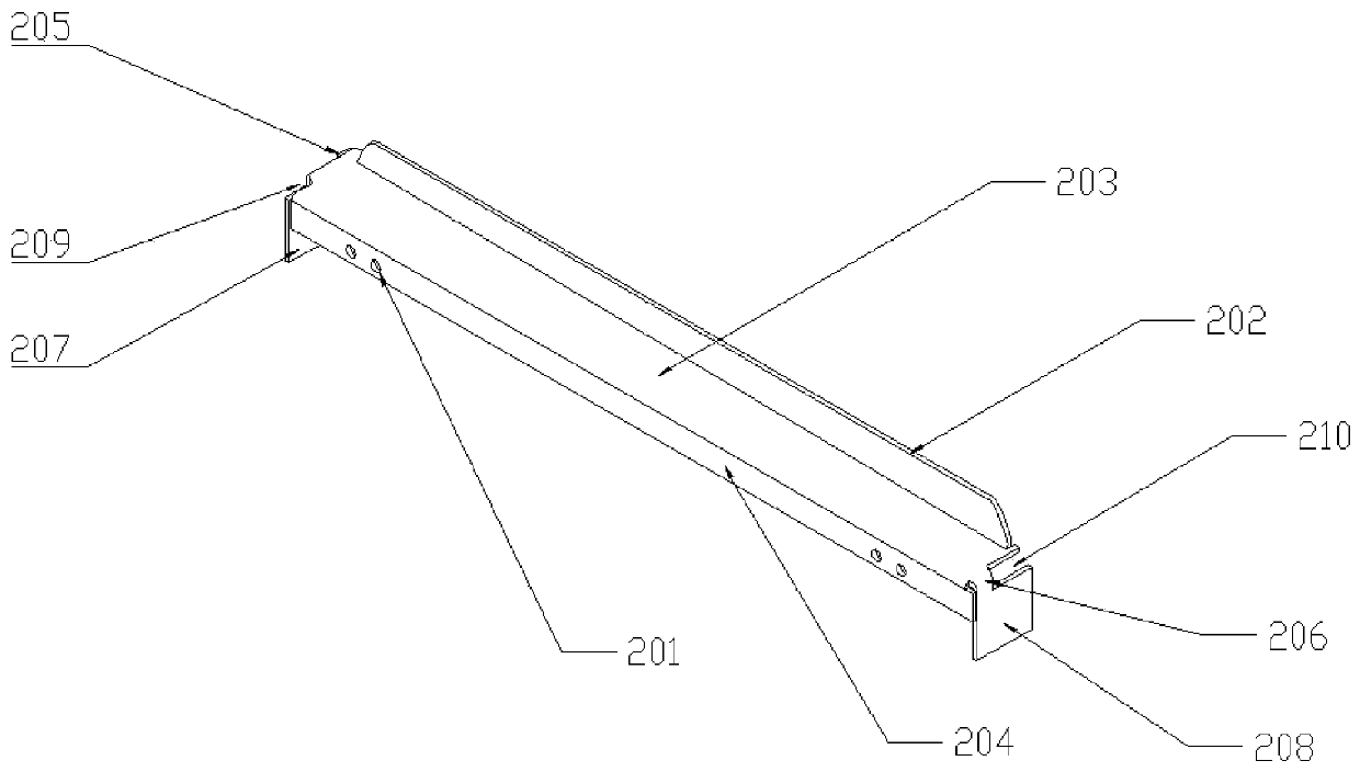
[0063] The difference between the floor of this embodiment and Embodiment 1 is that the first support frame 200 is a bent structure, such as figure 2 As shown, it includes a vertical upper plate 202, a first platform 203, and a first vertical front plate 204; wherein, the left and right ends of the first platform pass through the first connecting portion 205, the second connecting portion 206 and the first side plate 207 respectively. , The second side plate 208 is connected, the first side plate 207 has a first opening 209, the second side plate 208 has a second opening 210, the first opening 209 and the second connecting part 206 are in the opposite position, the second The two openings 210 are located opposite to the first connecting portion 205 , and the assembly holes 201 are symmetrically disposed on the left and right ends of the first vertical front panel 204 . The width of the first opening 209 is equal to the width of the second connecting portion 206, and the width...
Embodiment 3
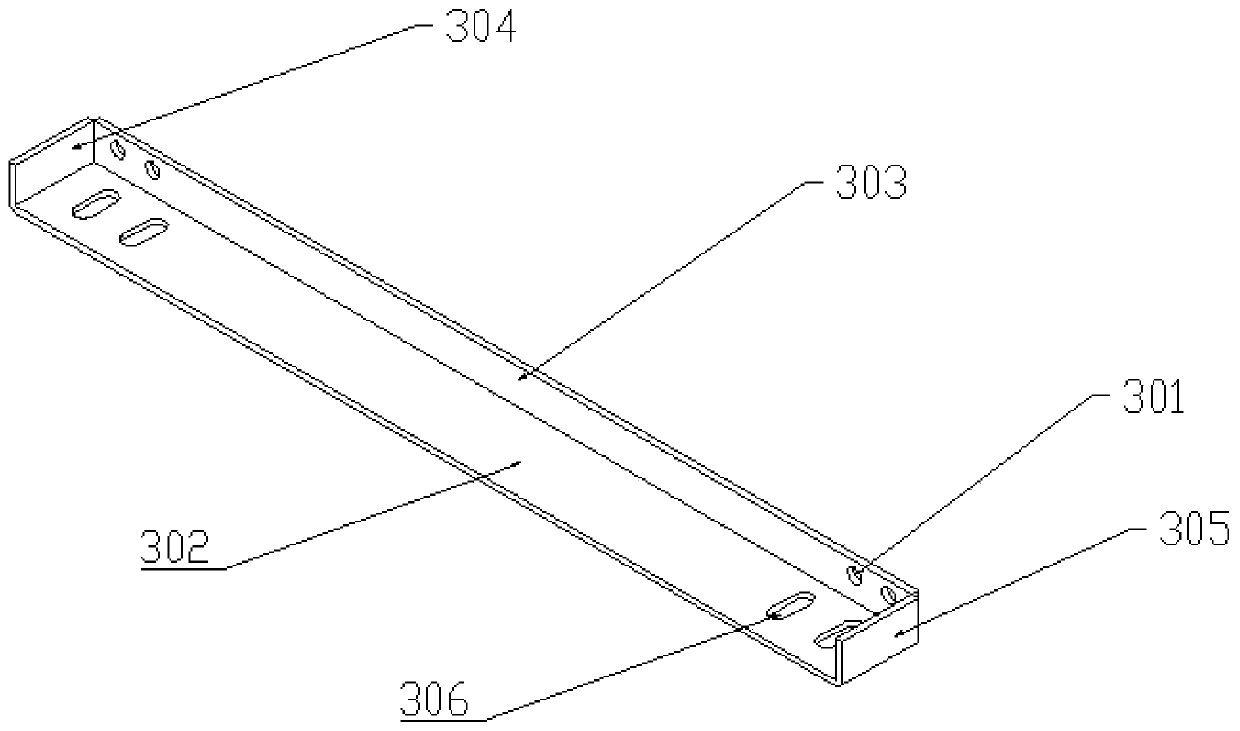
[0068] like Figure 1-7 As shown, the floor of this embodiment, on the basis of Embodiment 2, has five concave-convex structures, two concave structures 105 in the forelimb activity area, and a raised structure 104 between the two concave structures 105, and the rear limbs are active. There are three concave structures 105 in the area, and there is a raised structure 104 between two adjacent concave structures 105, which can more effectively prevent the sows from slipping. It has been verified by a large number of experiments that the sows do not slip. In order to keep the comfort of the sow lying down, the height difference between the highest point of the raised structure 104 and the lowest point of the sunken structure 105 should not be too large, it is set to 1.2cm, and the length of the raised structure 104 and the sunken structure 105 is set It is 12cm. On the first crossbeam 101, grooves 108 matching the width direction of the longitudinal support bar 102 are equidista...
PUM
 Abstract
Description
Claims
Application Information
 - R&D
- Intellectual Property
- Life Sciences
- Materials
- Tech Scout
- Unparalleled Data Quality
- Higher Quality Content
- 60% Fewer Hallucinations
Browse by: Latest US Patents, China's latest patents, Technical Efficacy Thesaurus, Application Domain, Technology Topic, Popular Technical Reports.
© 2025 PatSnap. All rights reserved.Legal|Privacy policy|Modern Slavery Act Transparency Statement|Sitemap|About US| Contact US: help@patsnap.com


