Light beam separation module, laser radar system and control method thereof

A technology of beam separation and laser radar, which is applied in the field of radar, can solve problems such as vehicles hitting target samples, laser radar missed detection, and casualties

Inactive Publication Date: 2019-07-12
SUTENG INNOVATION TECH CO LTD
View PDF7 Cites 1 Cited by
  • Summary
  • Abstract
  • Description
  • Claims
  • Application Information

AI Technical Summary

Problems solved by technology

[0003] However, the problem with using a polarizing beamsplitter is that if the depolarization effect of the target sample is not good, the echo beam reflected from the target sample is mainly P-polarized light, and the P-polarized light will only be reflected when it reaches the polarizing beamsplitter. The transmission reaches the position of the light source instead of being deflected by the polarization beam splitter to reach the laser detector of the detection module
[0004] This situation will lead to serious missed detection of lidar and affect the ranging results
If it is used in a self-driving vehicle, it may even cause the vehicle to hit the target sample, causing property damage and casualties

Method used


Image

  • Light beam separation module, laser radar system and control method thereof
  • Light beam separation module, laser radar system and control method thereof
  • Light beam separation module, laser radar system and control method thereof

Examples


Embodiment Construction

[0045] In order to make the purpose, technical solution and advantages of the present application clearer, the present application will be further described in detail below in conjunction with the accompanying drawings and embodiments. It should be understood that the specific embodiments described here are only used to explain the present application, and are not intended to limit the present application.

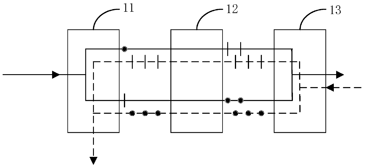
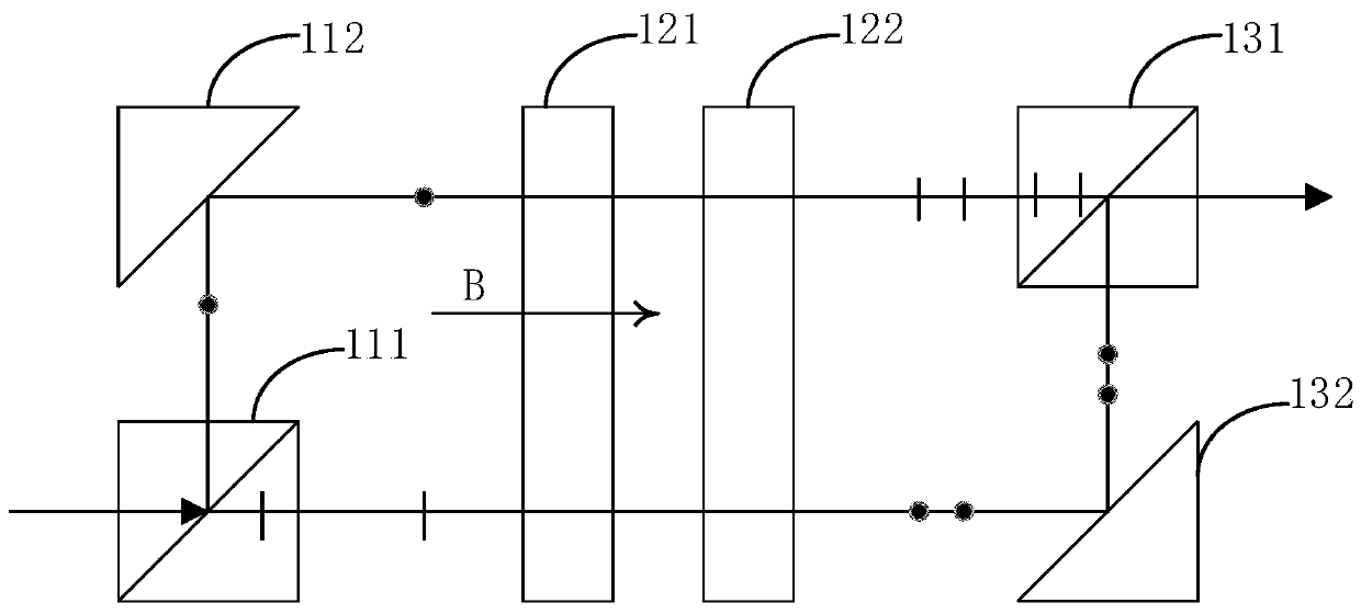
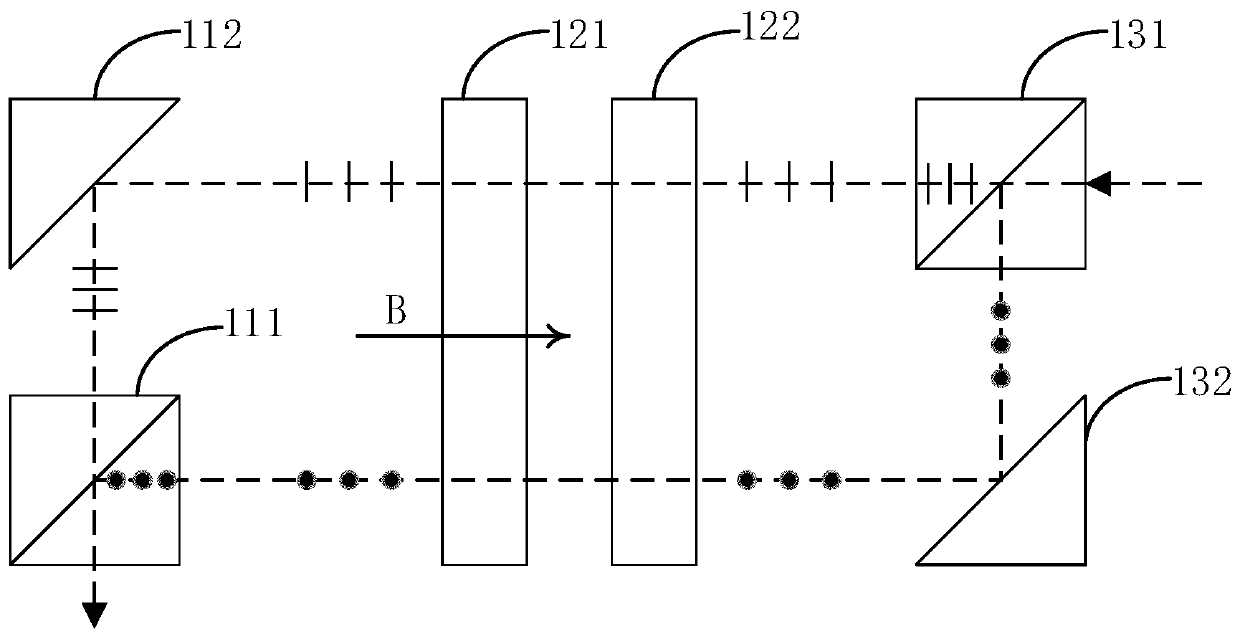
[0046] refer to figure 1 , shows a schematic structural diagram of a beam splitting module in an embodiment of the present invention. The beam splitting module 10 includes: a first beam splitting component 11 , an optical rotation component 12 and a second beam splitting component 13 .

[0047] The above-mentioned first beam splitting component 11 is used to split the incident beam emitted by the laser emitting module into the first P-polarized light and the first S-polarized light; the above-mentioned optical rotation component 12 is used to rotate the first P-polarized li...


PUM


Abstract

The invention relates to a light beam separation module, a laser radar system and a control method thereof. The light beam separation module comprises a first light splitting assembly, an optical rotation assembly and a second light splitting assembly. The first light splitting assembly is used for separating the incident light beam into first P polarized light and first S polarized light; the optical rotation assembly is used for rotating the first P polarized light into second S polarized light and rotating the first S polarized light into second P polarized light; the second light splittingassembly is used for mixing the second P polarized light and the second S polarized light into a first emergent light beam emitted to a target object; the second light splitting assembly is also usedfor separating the echo light beam into third P polarized light and third S polarized light; the optical rotation assembly is also used for maintaining the polarization directions of the third P polarized light and the third S polarized light; and the first light splitting assembly is also used for mixing the third P polarized light and the third S polarized light into a second emergent light beam which is emitted to a laser detection module. According to the embodiment of the invention, the laser detection module can receive the P polarized light, and the energy received by the laser detection module is increased.

Description

technical field [0001] The present application relates to the field of radar technology, in particular to a beam splitting module, a laser radar system and a control method thereof. Background technique [0002] With the development of science and technology, lidar is gradually applied to civilian products. For example, autonomous vehicles use lidar for ranging. LiDAR is mainly divided into two schemes: coaxial and off-axis. In the coaxial scheme, a polarization beam splitter is often used to split the outgoing beam and the echo beam. Polarization splitting can transmit almost all P-polarized light and deflect almost all S-polarized light. Combined with the transmitting module for P-polarized light output, the transmitting end can have better light energy transmittance. [0003] However, the problem with using a polarizing beamsplitter is that if the depolarization effect of the target sample is not good, the echo beam reflected from the target sample is mainly P-polarize...

Claims


Application Information

Patent Timeline
IPC IPC(8): G01S17/93G01S7/481G01S7/487G01S7/493
CPCG01S7/481G01S7/487G01S7/493G01S17/931
Inventor 罗斯特王吉刘夏魏威李兴华
Owner SUTENG INNOVATION TECH CO LTD
Why Eureka
Try Eureka