Gas on-line monitoring device and method for fiber grating gas sensing
A fiber grating and sensing technology, applied in the field of industrial sensing, can solve the problems affecting the accuracy and stability of fiber grating test results, the influence of artificial neural network pattern recognition, and the large difference between monitoring results and real values. Small size, reduced disturbance, and the effect of reducing collision friction
- Summary
- Abstract
- Description
- Claims
- Application Information
AI Technical Summary
Problems solved by technology
Method used
Image
Examples
Embodiment 1
[0061] 1. Fiber Bragg grating sensing element coated with gas-sensitive polymer film 1
[0062] Use a dropper to take a small amount of polyamic acid solution and drop it into the polytetrafluoroethylene mold. Using a fiber grating with a diameter of 125 μm, hold both sides of the grid area with both hands, and slowly immerse the grid section in the polyamic acid solution. When the grid area is completely When immersed in the solution, rotate the optical fiber slowly so that the surface of the grid area is completely and evenly attached to the polyamic acid solution. After 180s, slowly pull the grid area out of the solution and put it into the oven. Set the temperature of the oven to 90°C. After imidization and drying for 300s, repeat the steps of soaking-spinning-pulling-drying three times to prevent the formation of a complete film structure on the surface of the gate region due to the influence of surface tension.
[0063] 2. The basic structure of the test tube 4 and the v...
Embodiment 2
[0075] The gas on-line monitoring device for fiber grating gas sensing is basically the same as that in Embodiment 1, the difference is that the test tube 4 with the ventilation branch pipe 5 and 7 is refitted as the test tube 4 with the ventilation hole, and the specific operation is as follows: cancel the ventilation branch pipe 5, 7, and set dense air holes 8 at the bottom of the tubes on both sides of the test tube 4 at a distance of 50 mm from both ends, such as Image 6shown. At this time, because the vent hole 8 is provided at the bottom, even in a rainy environment, it can still keep the device from being soaked by rainwater; since the vent hole is between the optical fiber supporting stabilizer 2 and the sealing plug 6, the optical fiber supporting stabilizer 2. It can reduce the disturbance of the convective wind to the optical fiber and prevent the convective wind from acting on the radial direction of the optical fiber; at the same time, the dense ventilation holes...
Embodiment 3
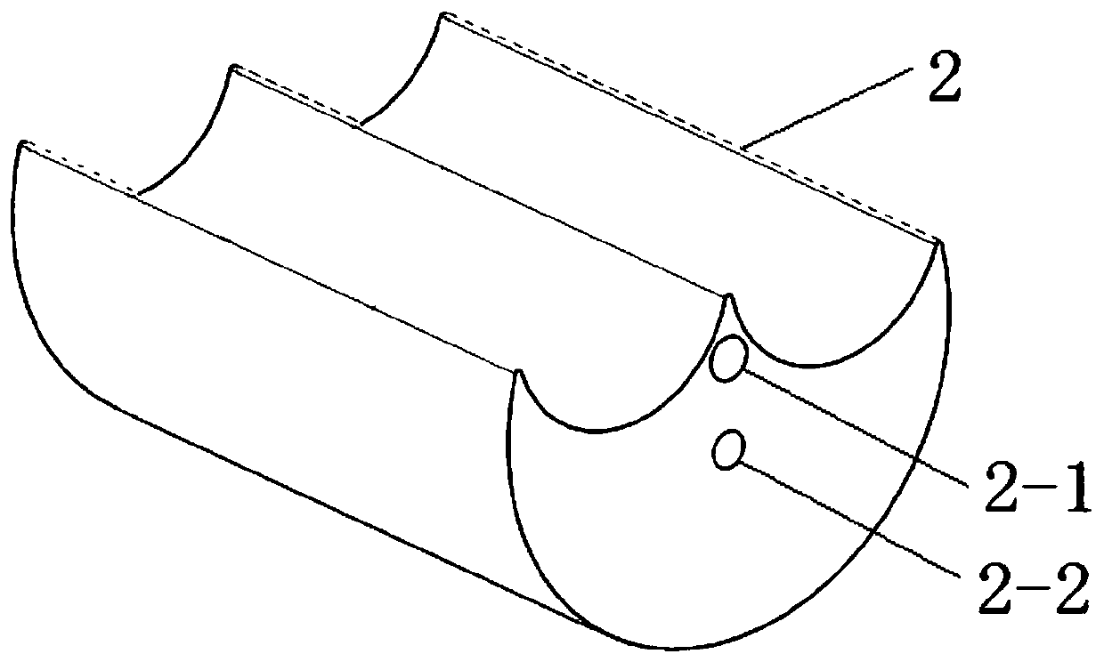
[0078] A gas on-line monitoring device for fiber grating gas sensing, comprising: a fiber grating sensing element 1, a test tube 4, a fiber grating support stabilizer 2, a positioning tube 3, a sealing plug 6, a fiber grating demodulator, Computer processor; the two ends of the test tube 4 are sealed by sealing plugs 6, the test tube 4 is provided with a fiber grating supporting stabilizer 2, and the fiber grating supporting stabilizer 2 is provided with a fiber grating sensing element 1 And the through holes 2-1, 2-2 through which the positioning tube 3 passes, the positioning tube 3 passes through the fiber grating supporting stabilizer 2, and is fixedly connected with the sealing plug 6 at at least one end;
[0079] The fiber grating sensing element 1 has an axial strain response characteristic, and is connected with a fiber grating demodulator and a computer processor in sequence.
[0080] Its using method is the same as embodiment 1.
PUM
| Property | Measurement | Unit |
|---|---|---|
| diameter | aaaaa | aaaaa |
| thickness | aaaaa | aaaaa |
| length | aaaaa | aaaaa |
Abstract
Description
Claims
Application Information
 - R&D
- Intellectual Property
- Life Sciences
- Materials
- Tech Scout
- Unparalleled Data Quality
- Higher Quality Content
- 60% Fewer Hallucinations
Browse by: Latest US Patents, China's latest patents, Technical Efficacy Thesaurus, Application Domain, Technology Topic, Popular Technical Reports.
© 2025 PatSnap. All rights reserved.Legal|Privacy policy|Modern Slavery Act Transparency Statement|Sitemap|About US| Contact US: help@patsnap.com


